Comparison of Laser Marking Control System Features
| Ezcad2 Laser Marking Control System | Ezcad3 Laser Marking Control System | |
| Software | EZCAD2 | EZCAD3 |
| Hardware | LMC Series Control Card | DLC Series Control Card |
| Connection Method | USB/PCIE | USB/PCIE/Ethernet |
| Axis Control | 2-Axis | 4-Axis/6-Axis |
| TCP/IP Variable Text Transmission | √ | √ Supports Remote Command Control |
| REMARK | √ | √ Supports Big Data Offline |
| High-Precision Scanner Calibration | √ | √ |
| Multi-file Processing | √ | √ |
| Multi-head Support | √ 8 – Galvo | √ 32 – Galvo |
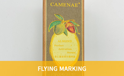
| Flying Marking | √ | √ 2-Axis flying |
| Camera Imaging | √ | √ |
| Secondary Development | √ | √ |
| Dynamic Focus | × | √ |
| 2.5D | × | √ |
| 3D | × | √ |
| Constant-Speed Marking | × | √ |
| Fast QR Code Marking | × | √ |
| Linear Changes in Power, Speed, Frequency | × | √ |
| Circular Arc Processing Enablement | × | √ |
| Fill Optimization | × | √ |
| Galvo Status Feedback | × | √ |
| Prevent the Growth of Light | × | √ |
| Double – galvo Control | × | √ |
| Online Firmware Update | × | √ |
| Galvo Protocol | XY2 – 100 | XY2 – 100, SL2 – 100 – 20, JCZ – 100 – 24, CANON – 64, RAYLASE – XY2 – 100 |
| Laser Types | FIBER, CO2, UV, YAG, SPI | Supports Various Mainstream Laser Types |
Ezcad2 Laser Marking Control System
Applied to general laser processing equipment.
Typical Applications
EZCAD3 Laser Marking Control System
Applied to high-precision micro/nano processing and high-power welding and cutting equipment.
Typical Applications


| Configurations | Details |
| Software Kernel | 32 Bit |
| Laser | Supports CO2, YAG, FIBER, SPI, etc., and can adjust current, pulse frequency, duty cycle, and other parameters based on different laser parameters through software |
| Red Light Display | Supports red light as an indicator |
| Password Control | Supports password protection to prevent unauthorized parameter changes |
| IO Control | Added port control functionality for easy automation of your machine |
| Galvo Calibration | Traditional trapezoidal correction, barrel (pillow) correction, and parallelogram correction with dedicated calibration software to achieve extremely precise calibration results |
| Fill | Circular fill, arbitrary angle fill, cross fill, adjustable margins, borders, and spacing, supports 3 layers of filling, with independent parameter settings for each layer |
| Editing Functions | Arbitrary curve text, arbitrary graphic drawing/editing, scatter/combine, group/ungroup, undo/redo, welding, trimming, cross, alignment, automatic curve connection, etc. |
| Text Input Function | Supports TrueType fonts, single-line fonts (JSF), dot matrix fonts (DMF), SHX, and user-created font libraries |
| 256 Layer Processing Parameters | Highly customizable for easy multi-parameter marking |
| Barcodes and QR Codes | Code39, EAN, PDF417, DATAMATRIX, QR, DATAMATRIX-GS1 etc. |
| Vector Files | PLT, DXF, Al, DST, SVG, GBR, NC, JPC, BOT |
| Bitmap Files | BMP, JPG, JPEG, GIF, TGA, PNG, TIF, TIFF |
| Variable Text | Fixed text, date, time, keyboard input, skipping numbers, list files, dynamic files, supports Excel sheets, TXT files, serial communication, and network communication |
| Multi-Language Support | Built-in Chinese, English, Korean, Japanese, French, German; can be easily localized by language packs for translation |
| Optional Features | Dual-axis splicing, flying marking, software secondary development |
| Configurations | |
| Software Kernel | 64 Bit |
| Laser | Supports CO2, YAG, FIBER, SPI, QCW, CW, etc. Can adjust current, pulse frequency, duty cycle, and other parameters through software. Real-time laser status display. Supports JCZ laser digital communication protocol 1.0, compatible with most lasers in the market. |
| Red Light Display | Supports red light as an indicator |
| Password Control | Supports password protection to prevent unauthorized parameter changes |
| IO Control | Added port control functionality for easy automation of your machine |
| Galvo Calibration | 3D calibration, traditional trapezoidal correction, barrel (pillow) correction, and parallelogram correction. Specialized software for precise calibration results. |
| Fill | Background fill, circular fill, arbitrary angle fill, cross fill, adjustable margins, borders, and spacing. Supports 8 layers of filling with independent parameter settings for each layer. |
| Editing Functions | Multi-layer, 3D curve marking, slicing, dynamic filling, 3D curve projection, surface wrapping, bitmap to embossing, arbitrary curve text, arbitrary graphic drawing/editing, scatter/combine, group/ungroup, undo/redo, welding, trimming, cross, alignment, automatic curve connection, etc. |
| Text Input Function | Supports TrueType fonts, single-line fonts (JSF), dot matrix fonts (DMF), SHX, and user-created font libraries |
| 256 Layer Processing Parameters | Highly customizable for easy multi-parameter marking |
| Barcodes and QR Codes | Code39, EAN, PDF417, DATAMATRIX, QR, PostNet, PL ANET, UK Royal Mail 4 state customer, AZTECCODE, MicroQRCODE, VERICODE, etc. |
| Vector Files | PLT, DXF, Al, DST, SVG, GBR, NC, JPC, BOT |
| Bitmap Files | BMP, JPG, JPEG, GIF, TGA, PNG, TIF, TIFF. Supports segmented processing. |
| Variable Text | Fixed text, date, time, keyboard input, skipping numbers, list files, dynamic files. Supports Excel sheets, TXT files, serial communication, and network communication. |
| Multi-Language Support | Built-in Chinese, English, Korean, Japanese, French, German. Easily localized by language packs for translation. |
| Optional Features | Four-axis point-to-point motion, dual-axis splicing, flying marking, software secondary development |
| Calibration Table | Supports loading and switching between up to 4 calibration tables simultaneously |
| Multi-Layer XY Plane Calibration | Improves XY plane calibration accuracy of 3D calibration |
| Offline Mark | Supports switching and processing of up to 16 offline layers |
| Online Circular Arc Interpolation Commands | Supports high-precision small circle processing |
| Three-Dimensional Model Files | STL, DXF |
| Processing Functions | Large-format dynamic focusing, projector positioning, multi-axis expansion, estimated processing time, ultra-fast point-like 2D barcode marking, uniform fill function, gradual power and speed control, circular and sine curve jitter, material parameter assistant function |
| Operation System | Windows 32/64 Bits | Windows 64 Bits |
| Programming Platform | X86 | X64 |
| Programming Language | C#, C++ | |
| Custom API | √ OPTIONAL | |
| Multi Head Library | √ OPTIONAL | √ |
| High Precision Calibration Library | × | √ OPTIONAL |
| Demo Code | √ | √ |
| User Manual | √ | √ |
| Note: EZCAD SDK can only be used with controller directly purchased from JCZ. Ezcad2 SDK only support LMC V4 Standard board (lite board not support) | ||
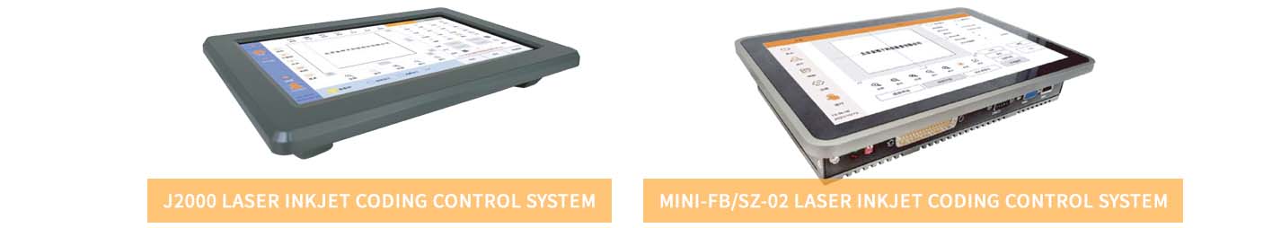
Laser Inkjet Coding Control System Feature
| J2000 | Mini-FB/SZ-02 | |
| EZCAD2 | × | √ |
| EZCAD3 | × | × |
| Static | √ | √ |
| Flying | √ | √ |
| Trigger Mode | √ | √ |
| Pipeline Mode | √ | √ |
| Three-Phase | √ | √ |
| Text | √ | √ |
| Secondary Development | √ | √ |
| Remote Upgrade | √ | √ |
| Fast Calibration | √ | √ |
| Vector Graphic | √ | √ |
| QR Code | √ | √ |
| TCP/IP | √ | × |
| Serial Communication | √ | × |
| Trigger Delay | √ | × |
| Trigger Shielding | √ | × |
| Screensaver | √ | × |
| Power Failure Protection | √ | × |
| Alarm Light | √ | × |
| Quick QR Code | √ | × |
| Axis Movement | × | × |
| Bitmap | × | √ |
Laser Inkjet Coding Control System Performance Overview
| Performance | J2000 | Mini-FB/SZ-02 |
| System | Linux | Windows 10 |
| Memory | 1GB | 2.00GB |
| Storage | 8GB | 32GB |
| Monitor Size | 10.1 inches | 10.1 inches |
| Maximum Resolution | 1280 * 800 | 1280 * 800 |
| Monitor Type | Resistive Screen | Capacitive Screen |
| Power Supply | 12-24V/2A | 12V/5A |
| Ethernet Port | 1 | 1 |
| Serial Port | RS232 * 1 | 1 |
| USB | 1 | 3 |
| IO | Input 2 Output 3 | Input 5 Output 9 / Input 4 Output 9 |
| Fiber/Digit Laser | Compatible | Distinguish |
System Overview
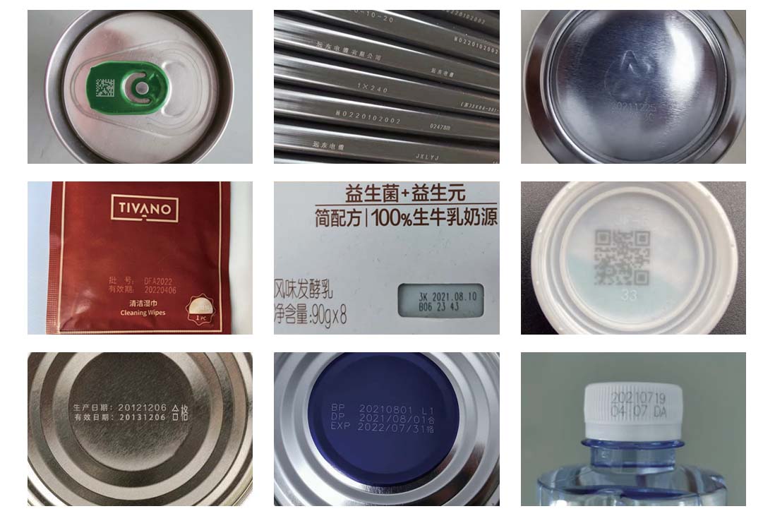
The J2000, and Mini series laser inkjet coding control systems feature full-coverage metal casings, strong interference resistance, a simple and user-friendly interface, and abundant functionality. This series can be widely used in various industries such as food and beverage packaging, tobacco, alcohol, dairy products, pharmaceuticals, cables, pipes, electronics, and more, for marking graphics and text including production dates, batch numbers, shifts, manufacturer names, and logos.
Typical Applications
System Overview
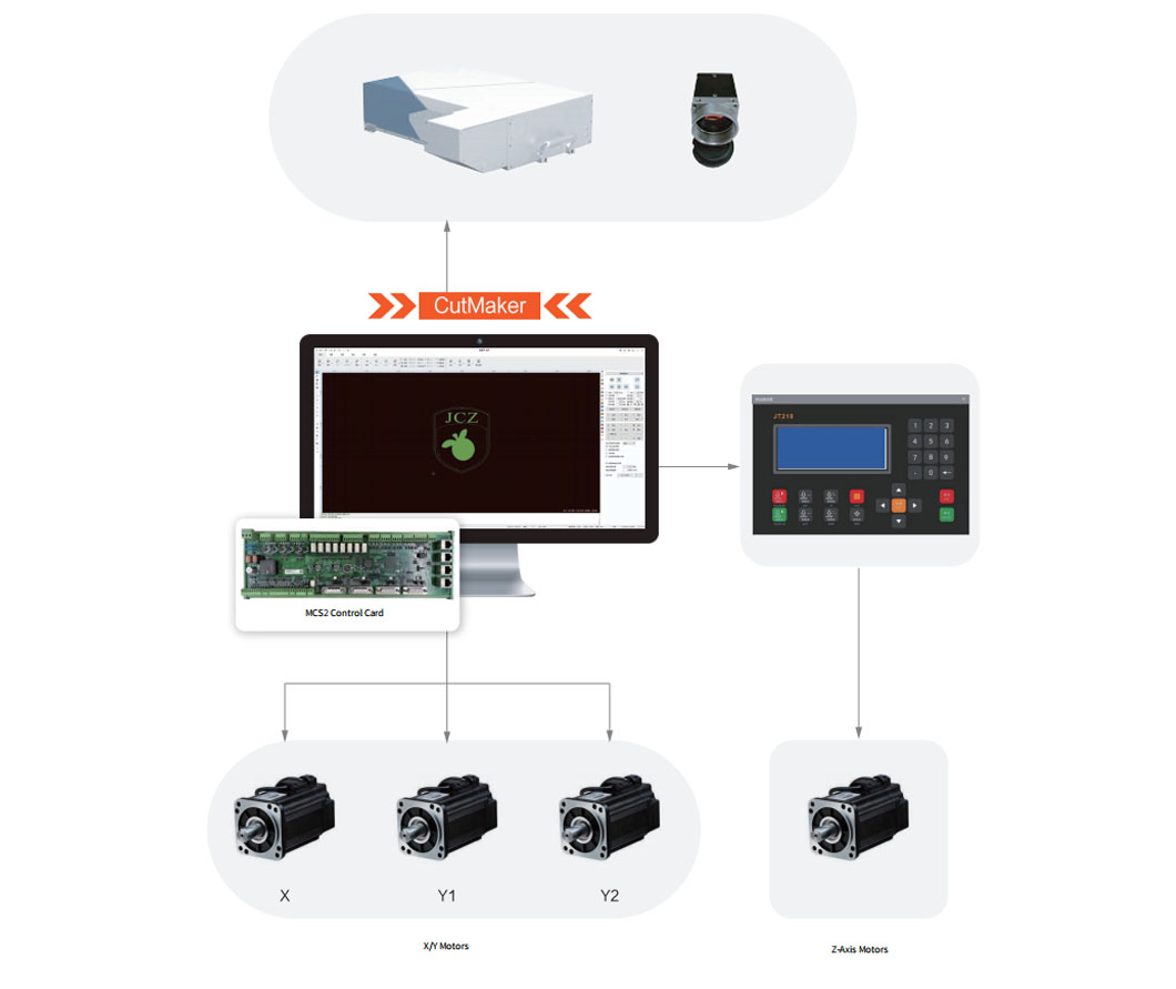
The laser cutting system is an independently developed control system by JCZ for fiber laser cutting. It features excellent motion control algorithms and process handling capabilities. This system is user-friendly, feature-abundant, stable, reliable, and offers strong performance. It can provide customers with comprehensive laser processing solutions and is widely used in industries such as advertising production, automotive manufacturing, 3C electronics, medical devices, and more.
| Maximum Operating Acceleration | 2 G | Maximum Operating Speed | 150 m/min |
| Positioning Accuracy | 0.001 mm | Repeated Positioning Accuracy | 0.003 mm |
| Special Output | 2 DA | Special input | 8 limitation switch/4 starting point |
| Output | 20 | Input | 16 |
System Advantages
System Architecture
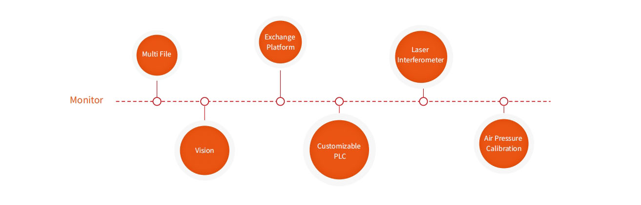
System Architecture
Application Cases
3C Electronics
Laser cutting is used for precision cutting or micro-hole processing of small components, whether they are made of metal or non-metal materials. It offers advantages such as high cutting precision, fast speed, and minimal heat impact. JCZ laser cutting system, with its multi-station and PLC capabilities, finds wide applications in the cutting of electronic products like mobile phones, laptops, and cameras. Its key advantages include precise processing dimensions, clear contours, especially for the precision machining of various high-end materials with high hardness, high brittleness, and high melting points. This effectively enhances the quality of processing, and compared to traditional tool cutting, contactless cutting improves the product yield.
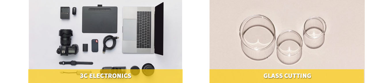
Glass Cutting
Cutting brittle materials like glass, representing a new application in the field of laser processing, is made possible with the use of ultra-fast lasers and JCZ laser cutting system with PSO functionality (500mm/s speed with arc accuracy of ±0.2um between points). This combination allows for high-speed and high-precision cutting of glass. When combined with post-cutting processes, it results in high-quality glass products with precise shapes.Cutting brittle materials like glass, representing a new application in the field of laser processing, is made possible with the use of ultra-fast lasers and JCZ laser cutting system with PSO functionality (500mm/s speed with arc accuracy of ±0.2um between points). This combination allows for high-speed and high-precision cutting of glass. When combined with post-cutting processes, it results in high-quality glass products with precise shapes.
Typical Applications

System Overview
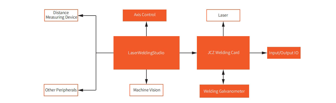
JCZ’s independently developed galvanometer welding system is suitable for medium and high-power welding applications. This system supports dual-beam control for circular laser beams, allowing for real-time position feedback and monitoring of the galvanometers. It ensures system security and reliability through features like access control and production modes. Additionally, the system integrates multiple-axis motion control and machine vision positioning functions, covering the requirements of multi-station, high-precision applications. It is characterized by high execution efficiency, excellent welding quality, strong adaptability, and ease of automation integration. It can be widely used in industries such as lithium batteries, photovoltaics, and 3C electronics.
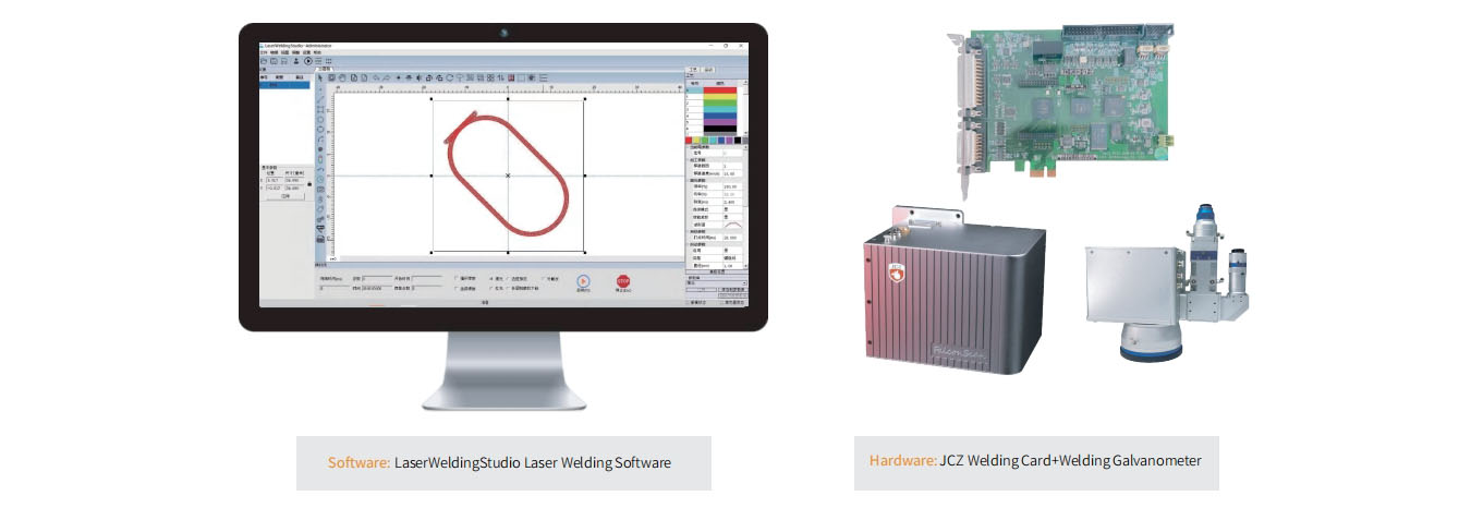
System Architecture
Welding Control Card
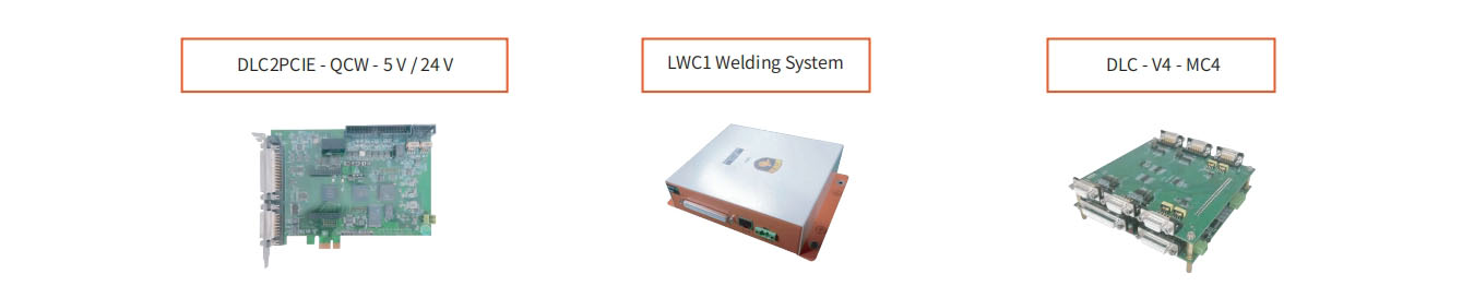
| Hardware Description | DLC2PCIE – QCW – 5V/24 V | LWC1 Welding System | DLC – V4 – MC4 |
| Upper Computer | PCIE | Ethernet | Ethernet |
| Communication Interface | 10 Input, 8 Output | 16 Input, 16 Output | 10 Input, 8 Output |
| Laser Interface | QCW5 V/24V | QCW 24 V | Multiple Laser Types |
Welding Scanner
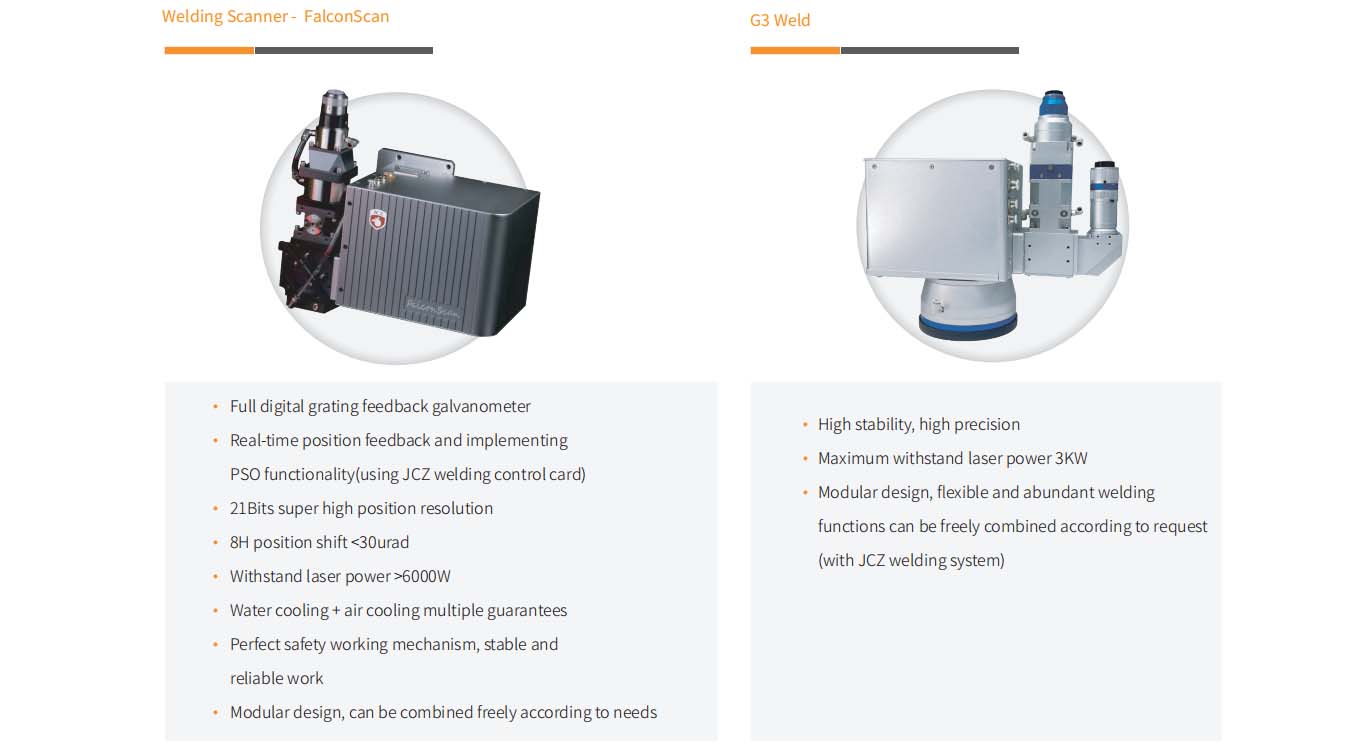
System Functions
Graphic processing Supports point, line, arc, spiral, rectangle, and arbitrary curve drawing, as well as DXF import
Teaching Allows mouse movement to offset galvanometer position, with welding location determined through coaxial vision
Multiple Graphics Files Enables combination processing of multiple graphics files and logic control through various triggering methods
Jitter Control Supports sine, spiral, figure-eight, and inverted figure-eight patterns, with adjustable density and speed of jitter trajectories
Linear Power Transformation Supports setting the length and ratio of the start and end to achieve gradual power increase and decrease
Power Curve Allows editing of the time-power curve to meet complex process scenario requirements
Dual Analog Control Editable analog waveform charts for center and ring light, enabling control of dual-beam laser
IO Includes input waiting and output control, providing flexible operation for task flow control
Motion Control Supports up to 4-axis stepper or servo motor drive control for various forms of automated welding integration
Machine Vision Customizable vision positioning assistance system to meet changing scenario requirements
Offline Mode Supports up to 8 offline files triggered through input pins
System Features
High Efficiency Supports multiple graphics files, multiple workstations, automatic optimization of multi-segment welding trajectory processing order, and galvanometer jump optimization.
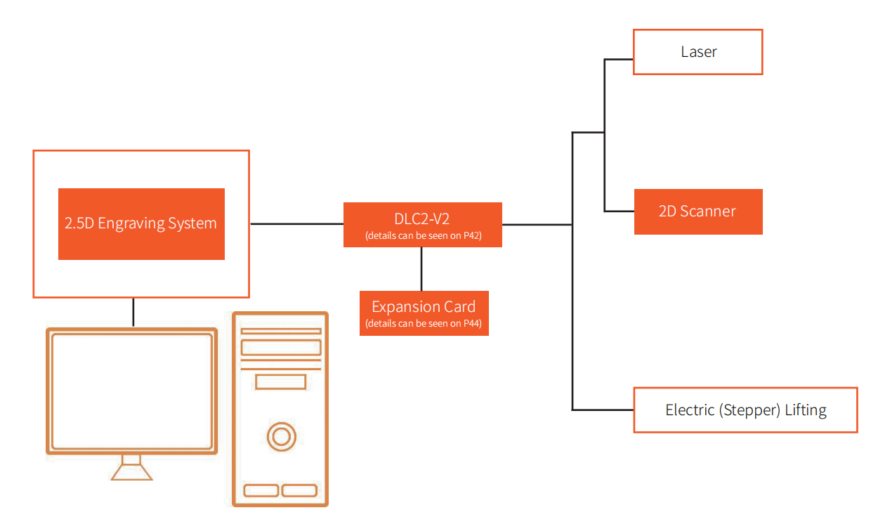
System Overview
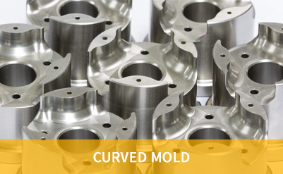
2.5D engraving system, using the latest self-developed Ezcad3 software and DLC2-M4-2D control card, combined with 2D digital scanning mirrors and electric(stepper) lifting. Compared to traditional methods, laser metal deep engraving offers advantages such as pollution-free operation, high precision, flexibleengraving content, and the ability to meet complex engraving processes. It is used in the laser deep engraving of products such as molds, nameplates, andhardware components.
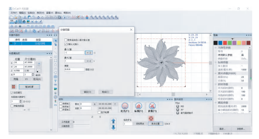
System Architecture
System Advantages
Introduction to the 2.5D Deep Engraving Control System Software User Interface: The software interface runs smoothly and is user-friendly. The system isoptimized for large-sized files and can support switching between positive and negative engraving for the same STL file. It offers various filling methods andallows for custom filling methods, providing users with options. The 2.5D deep engraving control system can reduce the production costs of equipment.
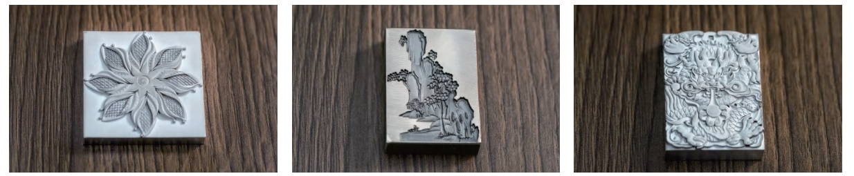
Typical Applications
System Overview
The 3D Printing Control System covers SLA/SLM/SLS and includes control software, axis control cards, and laser mirror control cards. The control software, version 2.0, has been refined by the team over many years and features several exclusive algorithms, earning high recognition in the market. For laser mirror and axis control hardware, dedicated hardware solutions have been developed specifically for SLA/SLM. The 3D Printing Control System provides users with a complete solution, simplifying equipment installation and usage, reducing overall equipment costs, and significantly improving installation efficiency and stability.
System Advantages
High Efficiency
Variable Power and Spacing Scanning Technology
By performing variable power and spacing scanning within a reasonable range, the processing efficiency is significantly improved, while reducing deformation, and maintaining a product density of over 99.7%.
Variable Power and Layer Thickness Scanning Technology
By performing variable layer thickness scanning within a reasonable range, the processing efficiency of the product is significantly improved while reducing deformation.
High Quality
Local Skin Recognition Technology
Various processes for recognizing upper and lower skins, as well as skin contours, result in high forming quality.
Local Thin Wall Filling
Identify all areas that regular filling cannot reach, compensate for them, and completely solve the problem of filling gaps.
Software and Hardware Integration Advantages
Multi-Scanner Calibration
By combining software and hardware, the complex calibration process is simplified while improving calibration accuracy. Calibration methods include fast 9-point calibration and precise 25-point caibration,significantly reducing user calibration time.
Zone Size Compensation
Combining hardware functionality to achieve different compensation sizes in different areas.
Power Gradient
Unique hardware functionality that completely solves defects caused by excessive laser intensity switching at the beginning and end.
System Architecture
Scheme 1
Scheme 2
System Overview
The Hercules control system integrates three-dimensional laser processing, robot control technology, and three-dimensional machine vision, covering laser marking, laser cutting, laser welding, and more. It can meet diverse requirements such as complex surfaces, large-sized workpieces, and flexible processing of multiple varieties. This system retains the high-speed and high-precision characteristics of galvanometer-based processing while incorporating the capabilities of robotics, enabling automated, intelligent, and flexible production. It finds wide applications in various industries, including precision molds, automotive components, smart wearables, mechanical hardware, 3C electronics, medical devices, and many others.
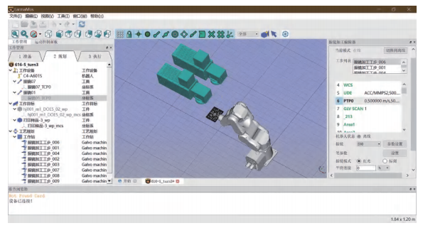
System Architecture

System Features
Flexibility
Automation of mechanical laser processing adaptable to changes in the workpiece.
High Precision
Laser processing with precise joining of multiple angles on complex-shaped workpieces.
High Efficiency
3D scanner control technology for efficient three-dimensional laser processing.
System Advantages
Intelligence
The Hercules control system has trajectory configuration capabilities, which can replace manual segmentation of processing content and manual design of robot motion posture trajectories. This system has an unknown detection function, which can solve problems such as manual verification of collisions, singular points, interference, and overtravel.
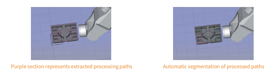
Subtractive Manufacturing
Eliminate the steps of projecting and wrapping 2D graphics onto 3D models. The processing graphics can be directly extracted from the surface of the 3D model, and the extracted 3D processing graphics support editing, moving, and rotating. This method effectively avoids the distortion issues associated with projection and wrapping algorithms.
Comprehensive Solution
The Hercules control system can perform calibration for the positions of the robot, mirrors, and workpiece in space. Based on the selected processing content, it automatically generates the laser processing paths, robot motion trajectory planning, and precise adjustments of the three-dimensional visual positions.
3D Laser Processing
The use of a scanner processing method can simultaneously enjoy the efficiency and accuracy of laser processing.
Robot Control
The Hercules control system supports control for more than 100 models from 12 different robot brands. It enables the creation of virtual scenes for a more realistic observation and design workflow.
Three-Dimensional Machine Vision
Equipped with proprietary three-dimensional machine vision technology developed in-house, making the debugging work simpler.
Application Cases
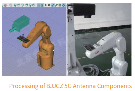
Processing of 5G Antenna Components
In 5G base station antennas, there are multiple complex cavity structures. Traditional laser scanning and focusing are typically performed in 2D planes. By combining a robotic arm with 3D dynamic scanner, implementing coordinated control, and utilizing spatial image positioning technology, we have perfectly solved the challenge of high-precision processing on complex surfaces with multiple degrees of freedom.
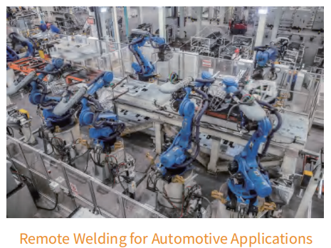
Remote Welding of Automotive Body Parts
Laser welding technology has found extensive applications in modern automotive body component production. The laser welding solution, based on robots and 3D scanning mirrors, combines the functions of robot control and 3D mirror control. It operates in a contactless manner during the welding process, offering flexibility in welding seam positioning. The robot’s movements are synchronized with the scanning of the laser mirror, effectively eliminating non-productive time caused by repetitive positioning before each welding segment. This maximizes the laser beam’s online time, enhancing production efficiency. This system is widely employed in welding automotive seat panels, instrument-related components, car door structural parts, trunk lids, new energy battery modules, plastic parts, and other products.
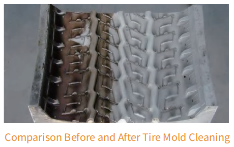
Laser Cleaning of Large and Complex Workpieces
Conventional laser cleaning equipment is mostly handheld, which makes it difficult to guarantee effective cleaning results and reliability. Therefore, it faces many limitations in demanding scenarios such as aircraft fuselages, tank bodies, reactors, and large rubber molds. Using the Hercules control system can meet these stringent requirements. By combining robots with mirror-based cleaning heads, it can be applied to the cleaning of large tire molds.
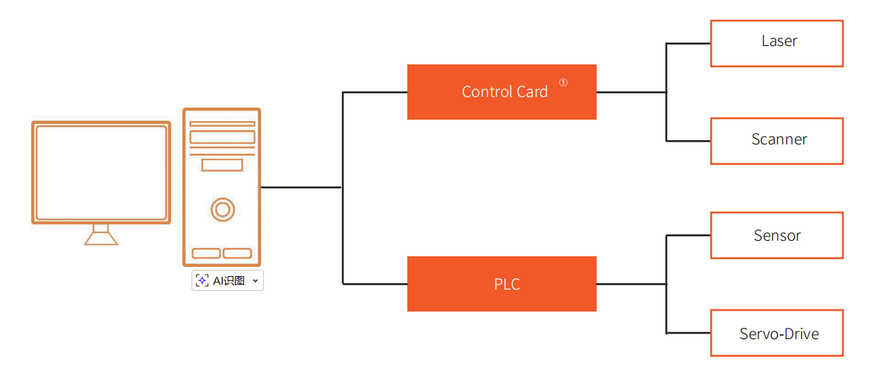
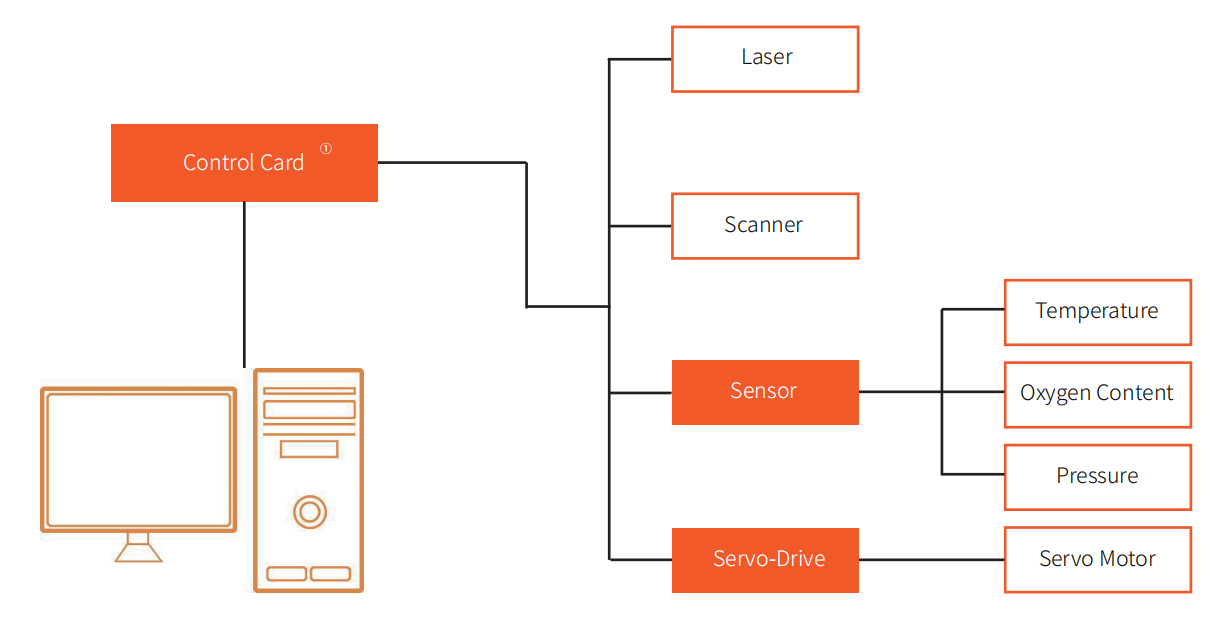
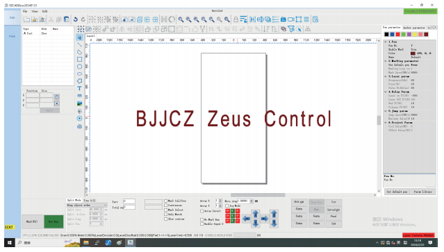
System Overview
The Intelligent-Continuous laser processing system is a universal laser processing system that integrates galvanometer control, machine vision, servo and stepper drive control technologies. This product features multi-axis coordination, various calibration combinations, high-precision camera positioning, and abundant CAD functions. It can be used in the field of efficient and precise processing and has developed corresponding Zeus subsystems for large-format laser engraving applications, PCB processing, and the glass industry, as well as PCB laser processing subsystems and glass laser processing subsystems.
System Architecture

System Features
High Precision
Combining multiple correction technologies including autofocus, visual correction, galvanometer correction, optical path correction, and platform correction, and combined with real-time fully closed-loop control, it can To achieve high-precision processing; measured at the end customer’s site, the positioning accuracy of the equipment’s motion axis is within ±10um, and the galvanometer correction accuracy is within ±5um. Under this condition, the overall linkage processing accuracy of the system can be within ±20um.
High Efficiency
The Zeus_V1 card uses a high-performance processor chip, has excellent data processing capabilities and real-time response characteristics, and can quickly process large amounts of data, and In the linkage scheme, the waiting time for no light output is reduced, thereby improving processing efficiency; for the characteristics of the motion axis performance being far worse than that of the galvanometer, avariety of methods have been developed. Radial decomposition algorithm reduces axis movement to improve processing efficiency; since sorting has a direct impact on processing efficiency, a variety of sorting algorithms are specially designed.
No Seams
The linkage solution solves the seam problem caused by cutting graphics by splicing method, so that non-filled drawings can be seamlessly seamed; it also solves the seam problem caused by filled drawings. The reason is that a corresponding sorting algorithm is speciallydesigned to solve the problem of patchwork of partially filled graphics.
High Adaptability To Drawings
The adaptive control method is used to make the system more intelligent and improve the adaptability of the system to different drawings while ensuring the processing effect and efficiency. User adjustment parameter control reduces the user threshold and improves user experience.
Abundant Craft Library
On the basis of the original process library, the processing process is optimized according to process requirements such as film cutting, and single-pass movement is realized in batches. Before ensuring the process effect, to ensure processing efficiency.
Full-Featured Laser And Galvanometer Control
The Zeus_V1 card integrates the mainstream laser and galvanometer control functions in the market, eliminating the need for laser adapter cards and galvanometer adapter cards, avoiding the risk of electrical interference, and is stable and reliable. Reliable, it supports up to 24-bit digital galvanometer closed-loop direct connection, and can fully utilize the performance of high-end accessories without backward compatibility.
Application Cases
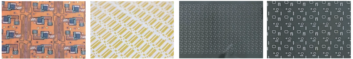
PCB Industry
As the precision processing production efficiency requirements of the PCB industry are getting higher and higher, the system linkage solution has been optimized and upgraded based on the splicing solution to realize laser, vibration Real-time fully closed-loop control of mirrors and platforms. On the premise of ensuring processing accuracy and process effects, production efficiency is greatly improved. Its application range can be used for rigid boards and flexible boards (FPC), cover film (CVL), rigid-flex board (RF) and other plates or materials for etching and cutting of QR codes, text and pictures. It can also be used for copper foil micro drills, hole application.
Metal Processing Industry
Metal processing industries such as stainless steel, elevator doors, nameplates, etc. have the characteristics of large format and high process requirements, and mainly process filling lines. When the galvanometer and platform are linked, During processing, a variety of new filling methods were developed to address the situation where the performance of the platform was far worse than that of the galvanometer; to address the joint problem caused by the insufficient accuracy of the actuator, a new filling method was developed. A variety of sorting methods have been developed to solve the problem of seaming, especially in the nameplate industry. The X and Y axis of the galvanometer and the X, Y and Z axis of the platform are processed together to achieve a deep carving effect. At the same time, the system also Provides functions such as platform correction, optical path correction, visual galvanometer correction and visual positioning, further improving processing accuracy.
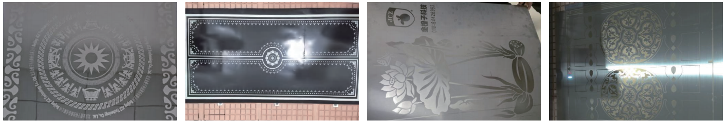
Glass Industry
The functional requirements of the glass industry are basically the same as those of stainless steel, elevator doors and other applications, but the process requirements are relatively low. Therefore, compared with stainless steel and other industries, the system has more and better applications. It is used in mirror paint removal, frosting, billboards and cleaning related industries. Since many customers have requested integrated paint removal and drilling, corresponding drilling functions have also been developed.
Display Industry
ITO film is a transparent conductive material that is widely used in touch display equipment, solar energy, outdoor glass and other fields. The circuit structure needs to be etched on its surface. Traditional chemical methods are not precise enough when making small-sized and high-density products. This system’s laser etching solution has obvious advantages. It can effectively control the spot size and calculate the expansion and contraction of the master. ization, so that the cutting drawings can automatically adapt to product size changes, thereby improving the yield rate. Just import the design file, in graphic editing and process parameter debugging can be completed within the software, which is simple, convenient and low-cost to use.
Medical Industry
This system has been applied in the medical industry. As patients change and drawings change frequently, users are very concerned about the debugging time and cost. Very sensitive, the system provides adaptive control methods, which significantly improves the quality of drawings while ensuring the processing effect and efficiency. Adaptability eliminates the need for user parameter adjustment and control, lowers user thresholds and improves user experience.

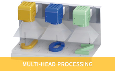
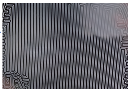
Single Light Source Multi-Galvo Processing Processing System
By using a beam splitter, the laser is precisely divided into multiple beams, which are then controlled by a synchronized processing system with multiple mirror heads in a JCZ single light source multi-scanner head setup for synchronous processing.
Using a single light source with multiple scanner heads allows for simultaneous processing of multiple products, resulting in stable processing performance. Compared to a single light source with a single scanner head setup, efficiency is significantly increased. This leads to increased profits and savings in labor and machine costs.
Multiple Light Sources, Multiple Scanner Heads
The multiple light source, multiple scanner head configuration uses either a JCZ DLC Ethernet card or an LMC control card. It utilizes one main card and multiple secondary cards of the same type (DLC Ethernet card supports up to 24 cards simultaneously, while LMC control card supports up to 8 cards simultaneously). Each scanner head requires individual laser configuration and can be used to process either the same or different content. This setup is suitable for situations where on-site environmental constraints necessitate control by a single computer, effectively saving space in the workspace.
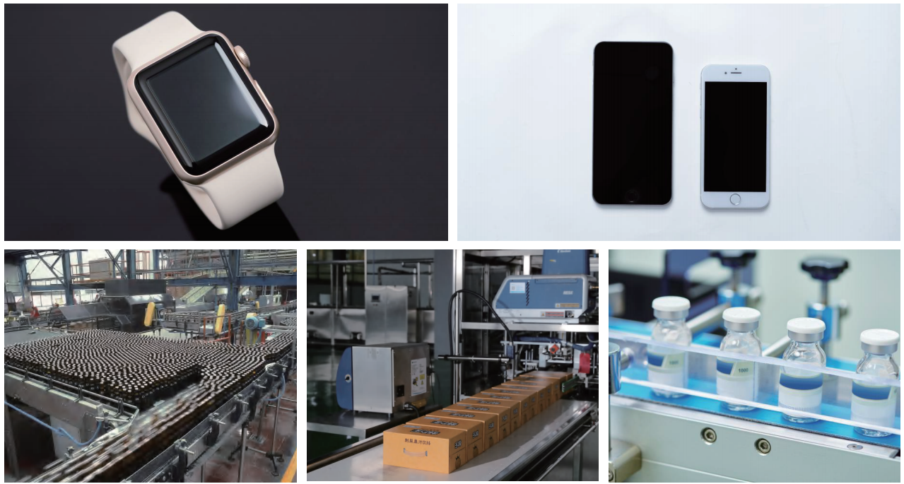
Typical Applications
Can be used for sapphire ink removal, automation lines in the food, beverage, and pharmaceutical industries, etc.
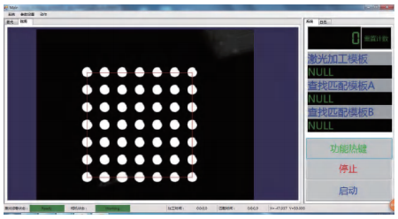
System Overview
By combining technologies such as visual localization, text recognition, defect detection, and laser marking, it is possible to reduce template design and production costs, achieve fast and accurate positioning, adapt to the production of various product types, effectively reduce process stations, increase production efficiency, and lower labor costs.
System Advantages
Custom Software:
Tailor-made for the target product, fully adapted to the production process. Easy to train and use. High user involvement provides a competitive advantage for ongoing sales.
Custom Hardware:
Overall design to avoid instability caused by user self-assembly.
Cost-Effective:
Use imported image libraries based on product characteristics and production requirements.
Matching Light Sources:
Effective Highlighting of Feature Points.
Machine Vision Localization Scheme Adaptation Diagram
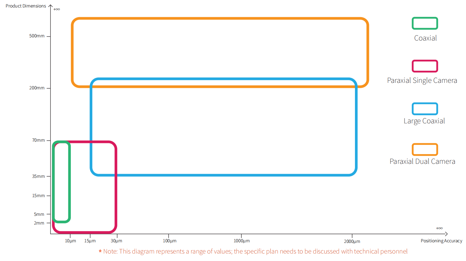
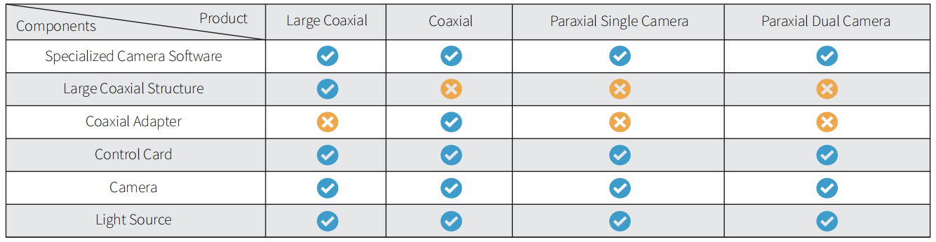
Large Coaxial
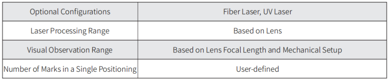
Function: Supports positioning of workpieces of any shape, edge detection, and common barcode recognition, suitable for positioning and processing of larger workpieces. Provides a complete machine vision positioning system that can support various types of lasers, meeting the processing requirements of various shapes. The hardware structure of this system is as follows: The camera optical path is unified with the laser optical path through a 45-degree mirror.
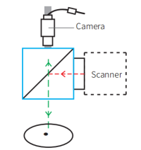
Coaxial
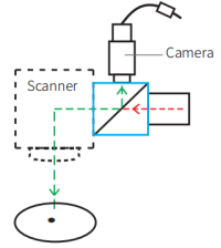
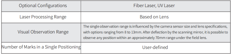
Function: In addition to supporting the positioning of workpieces of any shape, edge detection, and common barcode recognition, this system is suitable for highly precise positioning processing. It provides a comprehensive machine vision positioning system that can support various types of lasers and meet the processing requirements of various shapes, especially for video positioning processing of ultra-small workpieces. The hardware structure of this system involves using a reflector to align the camera’s optical path with the laser’s optical path on the same axis. When combined with a chromatic aberration-correcting scanning focusing lens, it ensures uniform and consistent laser spot within the scanning range.
Paraxial Single Camera
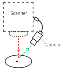
Function: It supports workpiece positioning of any shape, edge detection, and common barcode recognition. It is suitable for positioning and processing relatively small-sized workpieces. It provides a comprehensive machine vision positioning system that can support various types of lasers, meeting the processing requirements of various shapes.
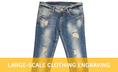
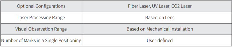
Paraxial Dual Camera
Function: In addition to supporting workpiece positioning of any shape, edge detection, and common barcode recognition, the paraxial dual-camera system is suitable for precision marking of large-sized workpieces. This system can extract templates when the camera is completely perpendicular to the workpiece. Two cameras simultaneously extract templates for matching, eliminating size restrictions on marked workpieces, allowing for large-scale marking.
![]()
Application Cases
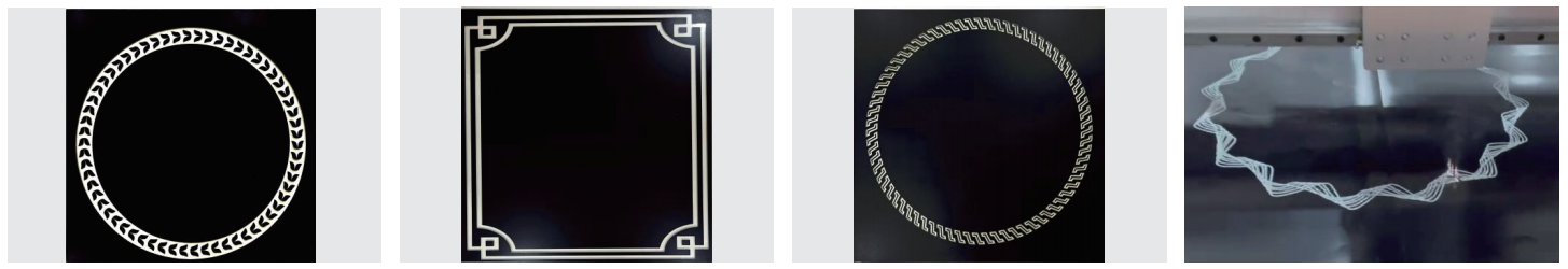
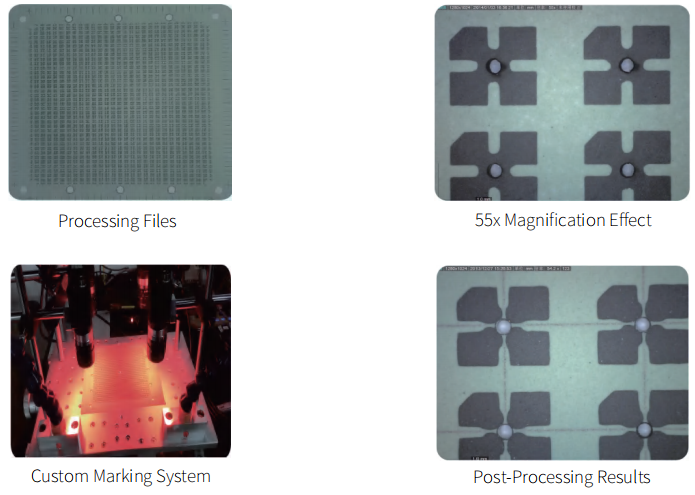
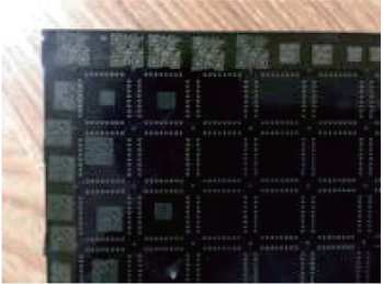
Four-Camera Positioning and Cutting
The processed sample consists of 29*37 holes with a diameter of 0.44mm. The material is soft, fragile, and prone to deformation. It has no elasticity, and its external dimensions vary. The positions of the small holes are also variable, making it impossible to achieve precise positioning using traditional mold fixation methods.
Technical Requirements
By using cross positioning at the four corners of the product, the laser cuts both horizontally and vertically through the center of each 0.4mm hole. The combination of the mirror and camera is installed as a single unit, avoiding potential collision and displacement issues. The positioning and cutting accuracy within a 130*130mm area is less than 0.02mm, ensuring stability, reliability, and minimal error. This system is designed to align perfectly with the product line, requiring users to adjust only two parameters when switching products.
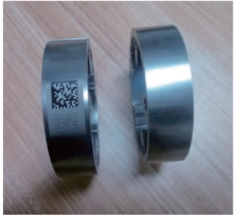
Coaxial Positioning & QR Code Recognition
QR codes are widely used in various fields of production and daily life due to their readability and large data capacity, serving as a form of identification in traceability systems.The traditional approach involves using a barcode scanner to read QR codes and then transmitting the barcode’s content to the laser processing system through communication. Now, we have integrated QR code recognition into the system, combined with a coaxial vision solution, to achieve a combination of positioning and scanning functions. Compared to the barcode scanner solution, this approach offers flexibility in configuring the scanning position without the need to consider additional space requirements for installing a barcode scanner. Additionally, it allows for direct data interaction within the software, eliminating the need for communication, thus improving efficiency and cost savings.
Processing Inspection
Verify whether the product has been processed with laser marking through visual inspection. Quick recognition, easy installation and setup, no need for on-site support from professional engineers.
Your Content Goes Here
Your Content Goes Here
Your Content Goes Here
Your Content Goes Here
Your Content Goes Here