Software")
This article introduces the main functions of a laser marking machine using EZCAD software developed by JCZ. The desktop fixed laser marking machine is one of the most basic models. Although the screenshots in this article may differ slightly from the version you are using, it will not affect your reference or operation.
The article includes five sections:
How to display grids (“boxes”) in the marking area
How to center files in the working area
How to draw a “+” symbol (positive electrode sign)
What to do if the marked characters are not 1:1 in size
How to switch red light modes and enable continuous red light marking
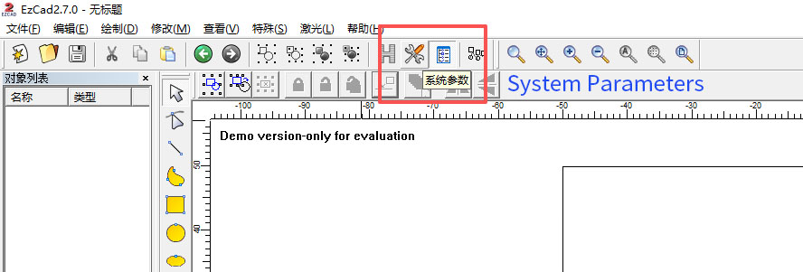
Let’s first take a look at the EZCAD interface.
1. How to Display Grids in the Marking Area
Click “System Parameters”, as shown below.
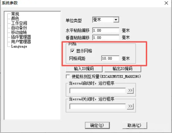
After the window pops up, check “Show Grid” and adjust the grid spacing according to your needs.

The common grid spacing value is 10.00 mm.
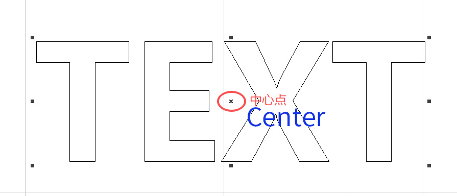
2. How to Center a File in the Working Area
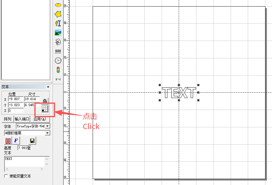
Whether it’s text or an image created in EZCAD, its default center point is located at the intersection of the crosshair. As shown below, the crosshair of the text represents the center of the graphic.
First, select the text, then click “Move to Origin”, as shown below.
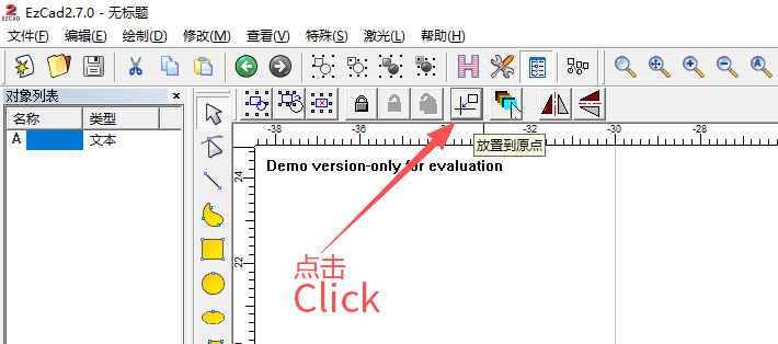
This will move the file to the exact center, but you may notice the coordinate display is not yet at the origin.

To fix this, click the black square (reference point) and move it to the center, as shown below.
A window will pop up.
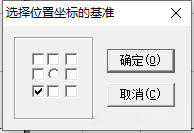
Move the checkmark “√” to the center and click OK.

The center point will now display as 0, 0.
3. How to Draw a “+” Symbol (Positive Electrode Sign)
Let’s assume the “+” symbol needs to be 10 mm horizontally and vertically, with a stroke width of 1 mm.
Click “Draw Rectangle”.

Draw two rectangles (their initial size does not matter).
After drawing, select “Select Graphics”.
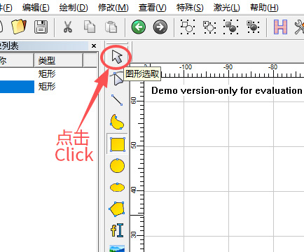
Select both rectangles and move them to the origin (the method is described above).


Modify their sizes according to your requirements.

If changing the X dimension causes the Y dimension to change simultaneously, unlock the proportional lock.
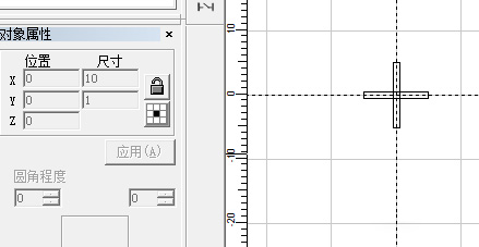
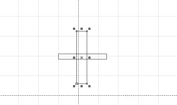
Here we define:
Horizontal bar: X = 10 mm, Y = 1 mm
Vertical bar: X = 1 mm, Y = 10 mm
If you try to fill the shape now, you will notice a hollow gap in the center.

To fix this, go back to the shapes.
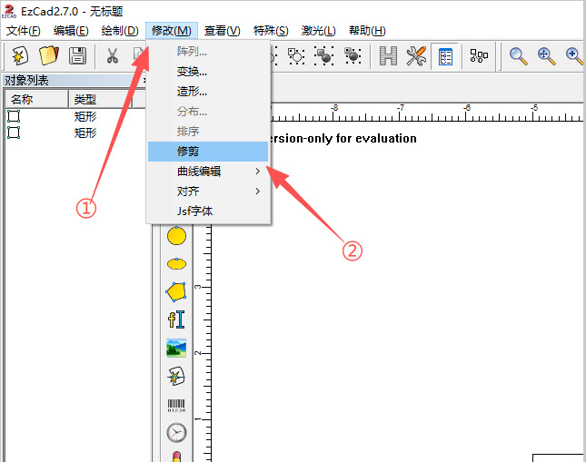
Click Modify → Trim.
Move the mouse to the overlapping lines.
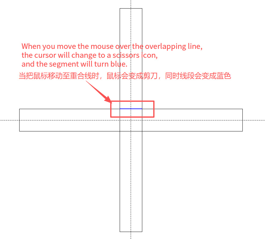
Trim the excess segments.
After trimming, select the shape again and click Group.
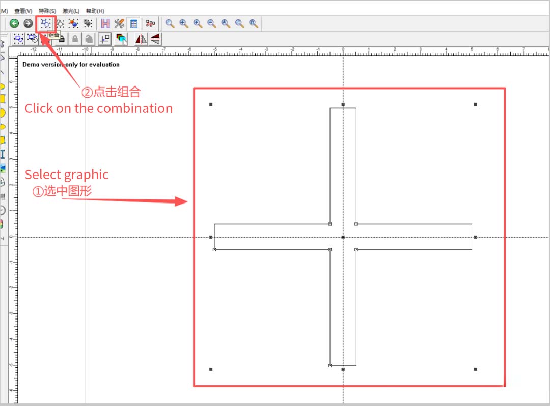
You will notice the object list changes from curves to a grouped object.
Next, click Modify → Curve Edit → Auto Join.
A popup will appear.
Click OK (or enter “0” if needed).
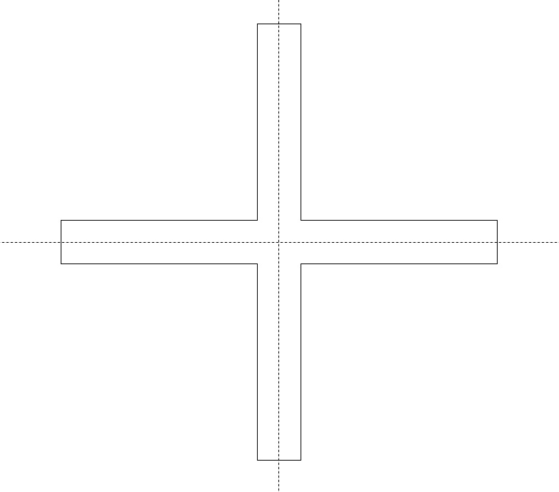
Now when you apply fill, the “+” symbol becomes a complete shape.
4. What to Do If the Marked Output Is Not 1:1 in Size
If you suspect the output is not accurate, perform a test.
Draw a 10×10 mm rectangle in the software and place it at the center.
Mark the rectangle and measure it with a ruler.
If the printed shape measures 14 mm, although the design is 10 mm, then calibration is required.
Open the software and click “Parameters F3”.
In the “Configuration Parameters” window, click “>>”.
Enter the target value and the actual measured value, then click OK.
This adjusts the scaling ratio.
Galvo 1 refers to the X-axis, and Galvo 2 refers to the Y-axis.
The steps for Y-axis calibration are the same.
Click OK to confirm.
Mark the test rectangle again—you should now see accurate 10 mm results.
5. Red Light Mode Switching & Continuous Red Light Settings
Open “Parameters F3”, then click “Other”.
Next, click “Red Light Display”.
Checking “Enable Outline Display” allows the red light to outline the actual marking shapes (text, numbers).
Unchecking it shows only the bounding box of the marking area.
Enable “Continuous Red Light Processing Mode” if you want an additional “Mark” button to appear after clicking Red Light.
If this option is unchecked, clicking Red Light will only show a “Stop” button.
Scan Head & 3D Galvo Head for Laser Systems
Best 3D Printer & SLA Machine for Industrial 3D Printing
Picosecond Lasers for Ultra-Precision Metal Marking & Engraving
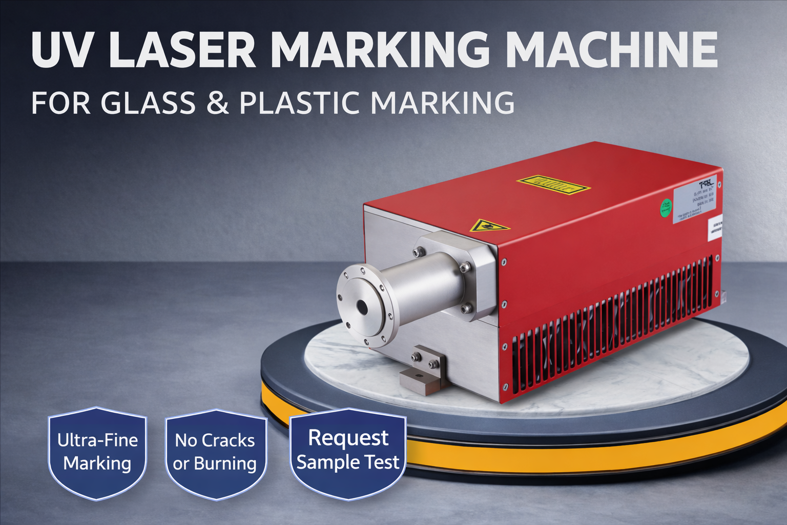
UV Laser Marking Machine for Glass, Plastic & High-Precision Applications
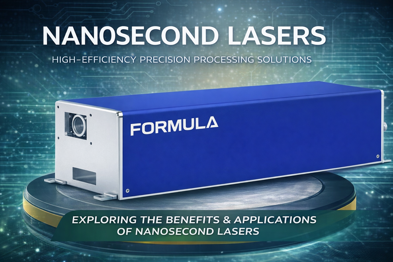
High Performance Nanosecond Lasers for Industrial Precision Processing