| 355nm Fused Silica | ||||||||
| Model | Input Aperture (mm) | Scan Field (mm) | Focal Length (mm) | Working Distance (mm) | Scan Angle (º) | Spot Size (µm) | Φ Diameter (mm) | Mount Thread |
| f-100Q-355 | 8 | Φ 90 (65 × 65) | 100 | 121.37 | ±25º | 8.35 | 90 | M85 × 1 |
| f-130-355 | 10 | Φ 113 (80 × 80) | 130 | 161.14 | ±25º | 8.5 | 90 | M85 × 1 |
| f-160Q-355 | 10 | Φ 140 (100 × 100) | 160 | 193.892 | ±25º | 10.3 | 90 | M85 × 1 |
| f-162B-355 | 12 | Φ 155 (110 × 110) | 162 | 200.82 | ±28º | 8.77 | 105 | M85 × 1 |
| f-170R-355 | 10 | Φ 148 (105 × 105) | 170 | 210.19 | ±25º | 11.04 | 90 | M85 × 1 |
| f-210R-355 | 10 | Φ 190 (135 × 135) | 210 | 250.55 | ±27º | 13.6 | 90 | M85 × 1` |
| f-210C-355 | 15 | Φ 185 (130 × 130) | 210 | 236.91 | ±25º | 9.1 | 120 | M85 × 1 |
| F-235-355 | 10 | Φ 146 (103 × 103) | 235 | 189.02 | ±17.4º | 15.27 | 90 | M85 × 1 |
| f-254Q-355 | 10 | Φ 247.5 (175 × 175) | 254 | 300.72 | ±25º | 16.4 | 90 | M85 × 1 |
| f-254C-355 | 14 | Φ 241.2 (175 × 175) | 254 | 318.21 | ±27º | 11.79 | 120 | M85 × 1 |
| f-255B-355 | 10 | Φ 221 (175 × 175) | 255 | 313.53 | ±28º | 16.57 | 120 | M85 × 1 |
| f-305B-355 | 16 | Φ 285 (201 × 201) | 305 | 365.55 | ±26.7º | 12.38 | 120 | M85 × 1 |
| f-330Q-355 | 10 | Φ 276 (195 × 195) | 330 | 390.77 | ±24º | 21.43 | 90 | M85 × 1 |
| f-330B-355 | 14 | Φ 288 (203 × 203) | 330 | 383.39 | ±25º | 15.3 | 120 | M85 × 1 |
| f-350C-355 | 10 | Φ 305 (216 × 216) | 350 | 409.61 | ±25º | 16.24 | 120 | M85 × 1 |
| f-470C-355 | 16 | Φ 410 (290 × 290) | 470 | 535.3 | ±25º | 19.08 | 120 | M85 × 1 |
| f-500C-355 | 14 | Φ 452 (320 × 320) | 500 | 568.14 | ±26º | 23 | 120 | M85 × 1 |
| f-580B-355 | 16 | Φ 509 (360 × 360) | 580 | 663.11 | ±25º | 25.22 | 120 | M85 × 1 |
| f-730Q-355 | 10 | Φ 661 (468 × 468) | 730 | 702.04 | ±26º | 47.4 | 90 | M85 × 1 |
| f-750-355 | 16 | Φ 735 (520 × 520) | 750 | 823.37 | ±28º | 32.3 | 120 | M85 × 1 |
| f-840-355 | 18 | Φ 850 (600 × 600) | 840 | 921.44 | ±29º | 30.3 | 120 | M85 × 1 |
| f-910-355 | 18 | Φ 933 (660 × 660) | 910 | 990.84 | ±29.5º | 42.2 | 120 | M85 × 1 |
| f-1090-355 | 18 | Φ1103 (780 × 780) | 1090 | 1177.9 | ±29º | 44.24 | 120 | M85 × 1 |
| f-1180-355 | 14 | Φ1130 (800 × 800) | 1180 | 1174.67 | ±28º | 54.76 | 120 | M85 × 1 |
| f-1280-14-355 | 14 | Φ 1251 (885 × 885) | 1290 | 1164.59 | ±28º | 59.4 | 120 | M85 × 1 |
| f-1450-14-355 | 14 | Φ 1272 (900 × 900) | 1450 | 1499.77 | ±25º | 67.29 | 120 | M85 × 1 |
| f-1550-10-355 | 10 | Φ 1513 (1070 × 1070) | 1549.953 | 1175.396 | ±28º | 174.7 | 120 | M85 × 1 |
| 532nm Fused Silica | ||||||||
| Model | Input Aperture (mm) | Scan Field (mm) | Focal Length (mm) | Working Distance (mm) | Scan Angle (º) | Spot Size (µm) | Φ Diameter (mm) | Mount Thread |
| f-160-10-515-540 | 10 | Φ 138 (98 × 98) | 160 | 57.33 | ±23.7º | 15.83 | 120 | M85 × 1 |
| f-170-510-550 | 10 | Φ 148 (100 × 100) | 170 | 221.09 | ±25º | 17.5 | 90 | M85 × 1 |
| f-225-510-550 | 18 | Φ 220 (156 × 156) | 225 | 247.51 | ±28º | 12.17 | 120 | M85 × 1 |
| f-255-14-510-550 | 14 | Φ 240 (170 × 170) | 255 | 367.81 | ±27.5º | 17 | 120 | M85 × 1 |
| f-350-14-510-550 | 14 | Φ 300 (212 × 212) | 350 | 283.37 | ±23.7º | 24.5 | 122 | M85 × 1 |
| f-450-14-510-550 | 14 | Φ 445 (315 × 315) | 450.15 | 526.392 | ±28º | 31.29 | 120 | M85 × 1 |
| f-840-20-510-550 | 20 | Φ778 (550*550) | 840 | 950.171 | ±28º | 40.9 | 120 | M85 × 1 |
| f-940-30-510-550 | 30 | Φ853 (603*603) | 940 | 854.306 | ±26.5º | 30.5 | 156 | M108 × 1 |
| f-1150-510-550 | 18 | Φ1131 (800 × 800) | 1150 | 1249.469 | ±29º | 62.3 | 120 | M85 × 1 |
| 532nm Optical Glass | ||||||||
| Model | Input Aperture (mm) | Scan Field (mm) | Focal Length (mm) | Working Distance (mm) | Scan Angle (º) | Spot Size (µm) | Φ Diameter (mm) | Mount Thread |
| f-63-532 | 8 | Φ 50 (35 × 35) | 63 | 58 | ±22º | 7.6 | 90 | M85 × 1 |
| f-80-532 | 10 | Φ 70 (50 × 50) | 80 | 91.6 | ±22º | 12 | 90 | M85 × 1 |
| f-100B-532 | 10 | Φ 82 (58 × 58) | 100 | 110.37 | ±25º | 9.7 | 90 | M85 × 1 |
| f-100R-532 | 12 | Φ 82 (58 × 58) | 100 | 112.77 | ±25º | 8 | 90 | M85 × 1 |
| f-120-532 | 12 | Φ 105 (74 × 74) | 120 | 132 | ±25º | 10 | 90 | M85 × 1 |
| f-160-532 | 12 | Φ 155 (110 × 110) | 160 | 183.18 | ±28º | 12.8 | 90 | M85 × 1 |
| f-160-532-58 | 12 | Φ 155 (110 × 110) | 160 | 186.88 | ±28º | 13 | 90 | M85 × 1 |
| f-165B-532 | 20 | Φ 162 (115 × 115) | 165 | 189.89 | ±28º | 8 | 120 | M85 × 1 |
| f-240B-532 | 20 | Φ 207 (145 × 145) | 237 | 252.31 | ±25º | 11.53 | 120 | M85 × 1 |
| f-254-10LNS-532 | 14 | Φ 235 (165 × 165) | 254 | 261.51 | ±28º | 16 | 105 | M85 × 1 |
| f-255-20-532 | 20 | Φ 233 (165 × 165) | 255 | 294 | ±26º | 12.5 | 120 | M85 × 1 |
| f-280-532 | 12 | Φ 273 (200 × 200) | 280 | 283.46 | ±28º | 22 | 90 | M85 × 1 |
| f-290-20-532 | 20 | Φ 268 (190 × 190) | 290 | 335.976 | ±26.5º | 14.1 | 120 | M85 × 1 |
| f-330B-532 | 14 | Φ 287 (203 × 203) | 330 | 397.46 | ±25º | 22.9 | 105 | M85 × 1 |
| f-330C-532 | 14 | Φ 287 (203 × 203) | 330 | 388.27 | ±25º | 22.9 | 120 | M85 × 1 |
| f-410-532 | 15 | Φ 400 (283 × 283) | 410 | 474 | ±28º | 26.6 | 120 | M85 × 1 |
| f-480-532 | 15 | Φ 448 (317 × 317) | 480 | 565 | ±26.8º | 31.15 | 120 | M85 × 1 |
| f-535B-532 | 20 | Φ 523 (370 × 370) | 535 | 623.67 | ±28º | 26.04 | 125 | M85 × 1 |
| 1064nm Fused Silica | ||||||||
| Model | Input Aperture (mm) | Scan Field (mm) | Focal Length (mm) | Working Distance (mm) | Scan Angle (º) | Spot Size (µm) | Φ Diameter (mm) | Mount Thread |
| f-100Q-1030-1080 | 10 | Φ 93 (66 × 66) | 100 | 126.49 | ±27.8º | 20 | 90 | M85 × 1 |
| f-100Q-1030-1080 | 10 | Φ 93 (66 × 66) | 100 | 126.49 | ±27.8º | 20 | 108 | M55 × 1; M85 × 1 |
| f-120A-14-1030-1080 | 14 | Φ 109 (77 × 77) | 120 | 158.18 | ±25º | 16.68 | 120 | M85 × 1 |
| f-160Q-1030-1080 | 10 | Φ 156 (110 × 110) | 160 | 192.5 | ±28.3º | 31.15 | 90 | M85 × 1 |
| f-160-1030-1080 | 12 | Φ 140 (100 × 100) | 160 | 209.01 | ±25º | 25.96 | 105 | M85 × 1 |
| f-160K-1030-1080 | 12 | Φ 140 (100 × 100) | 160 | 199.21 | ±25º | 22.25 | 120 | M85 × 1 |
| f-160A-14-1030-1080 | 14 | Φ 140 (100 × 100) | 160 | 203.3 | ±25º | 22.25 | 120 | M85 × 1 |
| f-160-15-1030-1080 | 15 | Φ 110 (78 × 78) | 160.259 | 183.61 | ±20º | 20.8 | 120 | M85 × 1 |
| f-160-20-1030-1080 | 20 | Φ 100 (71 × 71) | 160 | 203.53 | ±18º | 15.57 | 120 | M85 × 1 |
| f-170-10-1030-1080 | 10 | Φ 166(117.5 × 117.5) | 170 | 199.75 | ±28º | 33.1 | 90 | M85 × 1 |
| f-170-30-1030-1080 | 30 | Φ 98 (70 × 70) | 170 | 213.64 | ±25º | 11,03 | 146 | M102 × 1; M112 × 1 |
| f-170-30-1030-1080 | 30 | Φ 98 (70 × 70) | 170 | 215 | ±25º | 11.03 | 166 | M102 × 1; M112 × 1 |
| f-200-1030-1080 | 20 | Φ 173 (122 × 122) | 200 | 245.43 | ±24º | 20 | 132 | M85 × 1 |
| f-206-1030-1080 | 20 | Φ 170 (120 × 120) | 206 | 258 | ±23º | 20 | 120 | M85 × 1 |
| f-210-30-1030-1080 | 30 | Φ 141 (100× 100) | 210 | 269.234 | ±25º | 18 | 143 | M112 × 1 |
| f-254-1030-1080-Φ90 | 10 | Φ 247 (175 × 175) | 254 | 298.25 | ±28º | 49.5 | 90 | M85 × 1 |
| f-254-1030-1080-Φ105 | 12 | Φ 247 (175 × 175) | 254 | 296.96 | ±28º | 41.5 | 105 | M85 × 1 |
| f-254-1030-1080-Φ120 | 14 | Φ 247 (157 × 157) | 254 | 292.21 | ±25º | 35.3 | 120 | M85 × 1 |
| f-254-14-1030-1080 | 14 | Φ 248 (175 × 175) | 254 | 306.14 | ±28º | 35.25 | 126 | M85 × 1 |
| f-254-14-1030-1080 | 14 | Φ 248 (175 × 175) | 254 | 289.01 | ±28º | 35.25 | 126 | M85 × 1 |
| f-254-30-1030-1080 | 30 | Φ 181 (128 × 128) | 254 | 305.09 | ±21º | 16.48 | 157 | M102 × 1; M112 × 1 |
| f-254-30-1030-1080 | 30 | Φ 181 (128 × 128) | 254 | 304.09 | ±21º | 16.48 | 166 | M102 × 1; M112 × 1 |
| f-254D-30-1030-1080 | 30 | Φ 181 (120 × 120) | 254 | 319.36 | ±21º | 16 | 180 | M102 × 1; M112 × 1 |
| f-255-20-1030-1080 | 20 | Φ 216 (153 × 153) | 255 | 318.34 | ±25º | 30 | 132 | M85 × 1 |
| f-295Q-1030-1080 | 10 | Φ 287 (203 × 203) | 295 | 336.72 | ±28º | 57.44 | 90 | M85 × 1 |
| f-300-15-1030-1080 | 15 | Φ 262 (185 × 185) | 300 | 371.14 | ±25º | 38.9 | 120 | M85 × 1 |
| f-300-20-1030-1080 | 20 | Φ 262 (185 × 185) | 300 | 371.14 | ±25º | 29.2 | 140 | M85 × 1 |
| f-330E-1030-1080 | 20 | Φ 287 (203 × 203) | 330 | 396.25 | ±25º | 32.12 | 120 | M85 × 1 |
| f-330-30-1030-1080 | 30 | Φ 253 (175 × 175) | 330 | 392.64 | ±22º | 21.41 | 146 | M102 × 1; M112 × 1 |
| f-330-30-1030-1080 | 30 | Φ 253 (175 × 175) | 330 | 388.14 | ±22º | 21.41 | 166 | M102 × 1; M112 × 1 |
| f-330D-30-1030-1080 | 30 | Φ 253 (175 × 175) | 330 | 406.767 | ±22º | 21 | 180 | M102 × 1; M112 × 1 |
| f-350-1030-1080 | 20 | Φ 298 (210 × 210) | 350 | 429.55 | ±24º | 34.55 | 128 | M85 × 1 |
| f-420E-1030-1080 | 20 | Φ 424 (300 × 300) | 420 | 510.81 | ±24º | 41 | 120 | M85 × 1 |
| f-420-30-1030-1080 | 30 | Φ 355 (251 × 251) | 420 | 511.53 | ±24º | 27.26 | 140 | M112 × 1 |
| f-420-30-1030-1080 | 30 | Φ 355 (251 × 251) | 420 | 521.94 | ±24º | 27.53 | 166 | M102 × 1; M112 × 1 |
| F-460D-30-1030-1080 | 30 | Φ 382 (270 × 270) | 460 | 558.128 | ±24º | 29.9 | 186 | M102 × 1; M112 × 1 |
| f-750-30-1030-1080 | 30 | Φ 622 (440 × 440) | 750.042 | 888.527 | ±24º | 48.7 | 165 | M102x1 |
| 1064nm Optical Glass | ||||||||
| Model | Input Aperture (mm) | Scan Field (mm) | Focal Length (mm) | Working Distance (mm) | Scan Angle (º) | Spot Size (µm) | Φ Diameter (mm) | Mount Thread |
| f-63-1064 | 12 | Φ 50 (35 × 35) | 63 | 61.8 | ±22º | 10 | 90 | M85 × 1 |
| f-80-10LNS-1064 | 10 | Φ 70 (50 × 50) | 80 | 83.27 | ±22º | 15 | 90 | M85 × 1 |
| f-80-20LNS-1064 | 20 | Φ 70 (50 × 50) | 80 | 77.85 | ±25º | 7.7 | 105 | M85 × 1 |
| f-100M-1064 | 8 | Φ 100 (70 × 70) | 100 | 113.85 | ±28º | 24.3 | 60 | M55× 1 |
| f-100-10LNS-1064 | 12 | Φ 100 (70 × 70) | 100 | 118.49 | ±28º | 16.2 | 90 | M85× 1 |
| f-100R-1064 | 12 | Φ 87.99 (62 × 62) | 100 | 105.75 | ±25.2º | 16 | 90 | M85 × 1 |
| f-100-20-1064 | 20 | Φ 100 (70 × 70) | 100 | 104.85 | ±22º | 9.76 | 105 | M85 × 1 |
| f-100D-1064 | 20 | Φ 87 (62 × 62) | 100 | 103.37 | ±25º | 9.8 | 105 | M85 × 1 |
| f-120-30-1064 | 30 | Φ 105 (80 × 74) | 120 | 127.6 | ±25º | 15 | 140 | M112×1;M102×1;M95×1 |
| f-130-1064 | 12 | Φ 120 (85 × 85) | 130 | 141.96 | ±25º | 21.1 | 90 | M85 × 1 |
| f-160M-1064 | 8 | Φ 100 (71 × 71) | 160 | 178.66 | ±17.7º | 38.85 | 47 | M39 × 1; M55 × 1 |
| f-160-12LNS-1064 | 12 | Φ 155 (110 × 110) | 160 | 181.29 | ±28º | 25.9 | 90 | M85 × 1 |
| f-160R-1064 | 12 | Φ 155 (110 × 110) | 160 | 176.26 | ±28º | 25.9 | 90 | M85 × 1 |
| f-160H-20LNS-1064 | 20 | Φ 142 (101 × 101) | 160 | 180.72 | ±28º | 15.86 | 120 | M85 × 1 |
| f-163B-1064 | 12 | Φ 162 (113.3 × 113.3) | 163 | 186.45 | ±28º | 26.6 | 90 | M85 × 1 |
| f-163C-1064 | 20 | Φ 160 (113 × 113) | 163 | 182.15 | ±28º | 15.9 | 115 | M85 × 1 |
| f-168-36-1064 | 36 | Φ 146 (99.5 × 99.5) | 168 | 181.122 | ±25º | 9.1 | 163 | M112 × 1 |
| f-170-30-1064 | 30 | Φ 150 (110 × 100) | 170 | 198.31 | ±25º | 11.03 | 140 | M112×1;M102×1;M95×1 |
| f-173B-1064 | 12 | Φ 170 (120 × 120) | 173 | 197.51 | ±28º | 28 | 90 | M85 × 1 |
| f-188-1064 | 12 | Φ 185 (130 × 130) | 188 | 212 | ±28º | 30 | 90 | M85 × 1 |
| f-210A-1064 | 12 | Φ 212 (150 × 150) | 210 | 231.88 | ±28º | 34 | 90 | M85 × 1 |
| f-210B-1064 | 12 | Φ 205 (145 × 145) | 210 | 225.8 | ±28º | 25 | 90 | M85 × 1 |
| f-210-30 -1064 | 30 | Φ 185 (140 × 130) | 210 | 240.42 | ±25º | 13.63 | 140 | M112×1;M102×1;M95×1 |
| f-220-10LNS-1064 | 15 | Φ 216 (153 × 153) | 220 | 259.78 | ±28º | 29 | 90 | M55 × 1; M85 × 1 |
| f-220-20LNS-1064 | 20 | Φ 212 (150 × 150) | 220 | 241.55 | ±28º | 21.4 | 120 | M85 × 1 |
| f-254M-1064 | 8 | Φ 254 (180 × 180) | 254 | 299.42 | ±28º | 60 | 39 | M39 × 1; M55 × 1 |
| f-254B-1064 | 14 | Φ 245 (175 × 175) | 254 | 277.7 | ±28º | 35.3 | 90 | M85 × 1 |
| f-254-10LNS-1064 | 16 | Φ 245 (175 × 175) | 254 | 281.14 | ±28º | 30 | 105 | M85 × 1 |
| f-254-20LNS-1064 | 20 | Φ 245 (175 × 175) | 254 | 271.94 | ±25º | 24.8 | 120 | M85 × 1 |
| f-254-30-1064 | 30 | Φ 222 (175 × 155) | 254 | 284.58 | ±25º | 20 | 140 | M112×1;M102×1;M95×1 |
| f-255-8.5B-1064 | 15 | Φ 268 (190 × 190) | 255 | 292.94 | ±30.2º | 33.1 | 99.5 | M85 × 1 |
| f-260-1064 | 12 | Φ 255 (180 ×180) | 260 | 287.54 | ±28º | 42.5 | 90 | M85 × 1 |
| f-290-1064 | 12 | Φ 283 (210 × 210) | 290 | 348.52 | ±28º | 47 | 90 | M85 × 1 |
| f-300D-1064-58 | 10-14 | Φ 295 (208 × 208) | 300 | 360.86 | ±28º | 35 | 90 | M85 × 1 |
| f-330-1064 | 12 | Φ 325 (230 × 230) | 330 | 383.93 | ±28º | 53 | 90 | M85 × 1 |
| f-330C-1064 | 16 | Φ 325 (230 × 230) | 330 | 387.61 | ±28º | 40 | 120 | M85 × 1 |
| f-330-30-1064 | 30 | Φ 325 (230 × 230) | 330 | 376.42 | ±28º | 21.2 | 140 | M112×1;M102×1;M95×1 |
| f-350C-1064 | 20 | Φ 345 (244 × 244) | 350 | 417.81 | ±28º | 34 | 120 | M85 × 1 |
| f-420-10LNS-1064 | 10 | Φ 419 (296 × 296) | 420 | 481.32 | ±28º | 82 | 90 | M85 × 1 |
| f-420B-1064 | 20 | Φ 410 (290 × 290) | 420 | 486.08 | ±28º | 40.8 | 120 | M85 × 1 |
| f-420-30-1064 | 30 | Φ 410 (290 × 290) | 420 | 491.03 | ±28º | 27.3 | 140 | M112×1; M132×1 |
| f-430B-1064 | 20 | Φ 425 (300 × 300) | 430 | 497.77 | ±28º | 41.9 | 120 | M85 × 1 |
| f-515-1064 | 20 | Φ 565 (400 × 400) | 515 | 570.35 | ±31.5º | 50.1 | 120 | M85 × 1 |
| f-525-1064 | 20 | Φ 568 (402 × 402) | 525 | 604.73 | ±31.5º | 51.1 | 125 | M85 × 1 |
| f-580-1064 | 24 | Φ 566 (400 × 400) | 580 | 670.19 | ±28º | 47 | 125 | M85 × 1 |
| f-815-1064 | 24 | Φ 800 (565 × 565) | 815 | 899.83 | ±28º | 66 | 125 | M85 × 1 |
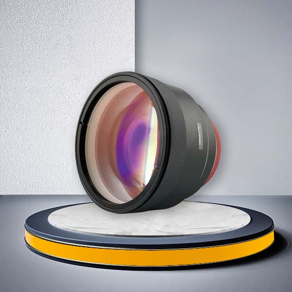
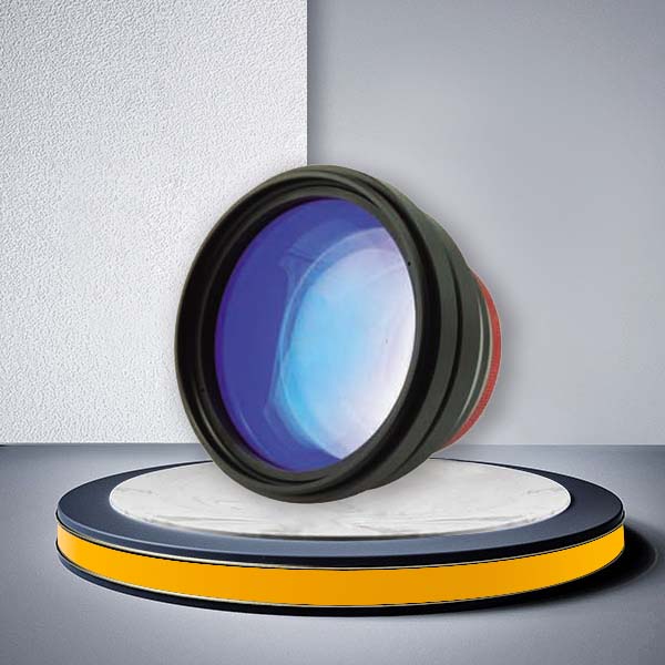
F-Theta Scan Lens for Industrial Laser Marking and Galvo Systems
An F-Theta Scan Lens is the final focusing optic in a typical 2D galvo laser system. It converts the angular movement of the galvo mirrors into a controlled position across a flat working field, allowing the laser system to mark, engrave, etch, clean or drill over a defined area without mechanically moving the workpiece.
JCZ supplies flat-field F-Theta Scan Lens configurations for common industrial laser wavelengths including 355 nm UV, 532 nm green and 1064 nm / 1030–1080 nm infrared laser systems. Multiple focal lengths, input apertures, scan fields, working distances, spot sizes and mounting threads are available, allowing machine builders and system integrators to match the lens to the laser source, galvo scanner and required processing area rather than selecting a lens by focal length alone.
Choose an F-Theta Scan Lens by Laser Wavelength
Wavelength compatibility should be confirmed before considering focal length or scan field. An F-Theta Scan Lens is designed and coated for a defined wavelength range, and using a lens outside that range can reduce transmission and compromise processing performance.
355 nm F-Theta Scan Lens
355 nm configurations are intended for UV laser processing. They are commonly considered for applications where a smaller focused spot and lower thermal impact are important, including fine marking, electronics processing, PCB-related work, glass or polymer processing and other precision applications.
The current range includes fused silica options with different input apertures, focal lengths, working distances and scan fields.
532 nm F-Theta Scan Lens
532 nm green laser systems require an F-Theta Scan Lens optimized for the green wavelength range. JCZ offers both fused silica and optical glass configurations for 532 nm applications.
When selecting a green laser scan lens, compare the required processing area with the available focal length, input aperture and working distance rather than assuming that lenses with similar external dimensions are interchangeable.
1064 nm / 1030–1080 nm F-Theta Scan Lens
1064 nm and 1030–1080 nm configurations cover common infrared and fiber-laser-based galvo systems. The current product range includes a broad selection of focal lengths and scan fields as well as different aperture and mounting options.
These F-Theta Scan Lens models can be considered for general industrial laser marking, engraving, coding, traceability and material processing systems using a compatible infrared laser source.
How to Select the Right F-Theta Scan Lens
A replacement or new F-Theta Scan Lens should be selected as part of the complete optical system. The correct choice depends on the laser source, beam diameter, galvo scanner, marking area and required feature size.
1. Start with the Laser Wavelength
First confirm the actual laser wavelength:
355 nm – UV laser systems
532 nm – green laser systems
1064 nm / 1030–1080 nm – infrared and common fiber laser systems
Do not select only by mechanical size or focal length. Two lenses with similar dimensions can use different optical materials or coatings and be designed for different wavelengths.
2. Match the Input Aperture to the Beam and Galvo Scanner
The input aperture should be considered together with the laser beam diameter reaching the scan lens and the aperture of the galvo scanner.
A beam that is too large for the optical aperture can be clipped. A significantly undersized beam may not use the available aperture efficiently and can affect the achievable focused spot.
For new machine designs, the scan head and lens should therefore be selected together.
JCZ offers multiple 2D galvo configurations for different wavelength, speed and aperture requirements.
3. Balance Focal Length, Scan Field and Spot Size
Focal length is one of the most important purchasing parameters, but a longer focal length is not automatically better.
In general, increasing focal length allows a larger working field and often provides a longer working distance. The trade-off is that the focused spot typically becomes larger when the other optical conditions remain similar.
A shorter focal length is generally preferred when:
fine marking detail is more important than maximum marking area;
a smaller focused spot is required;
the required scan field is relatively small.
A longer focal length is generally preferred when:
a larger marking or processing area is required;
the process needs additional clearance between the lens and workpiece;
processing more area without repositioning the part is more important than obtaining the smallest possible spot.
This is why the F-Theta Scan Lens should be selected from the required marking field backward rather than simply choosing the largest available focal length.
Scan Field Is Not the Only Specification That Matters
Two F-Theta lenses can provide similar nominal marking areas but still behave differently in a machine because of differences in input aperture, focal length, scan angle, working distance and spot size.
When comparing models, check the complete combination of:
laser wavelength;
input aperture;
required X-Y scan field;
focal length;
working distance;
scan angle;
spot size;
lens housing diameter;
mounting thread.
The specification tables on this page provide these values for the available 355 nm, 532 nm and infrared configurations so that system builders can compare models using actual optical and mechanical requirements.
Fused Silica or Optical Glass?
The product range includes both fused silica and optical glass configurations for selected wavelengths.
Fused silica is commonly considered where UV performance, thermal stability or demanding laser operating conditions are important. Optical glass can be a practical choice for many standard industrial marking systems when its wavelength and operating requirements match the application.
The material alone should not determine the purchase. Laser wavelength, beam characteristics, power level, focal length, required scan field and total system configuration still need to be checked together.
If you are replacing an existing scan lens, provide the current lens model or optical specifications so that the replacement can be matched more accurately.
Working Distance and Machine Integration
Working distance determines the approximate mechanical spacing required between the F-Theta Scan Lens and the processing plane.
This becomes particularly important when the machine must accommodate:
fixtures or rotary devices;
parts with raised features;
production-line conveyors;
protective enclosures;
vision systems;
large components requiring additional clearance.
A lens with a suitable scan field but insufficient mechanical clearance may not fit the actual machine structure.
Mounting thread must also be verified before replacement. Many models in the current range use M85 × 1, while other configurations use different thread sizes such as M39, M55, M95, M102, M112 or other interfaces depending on the lens design.
Do not assume that two F-Theta lenses with the same focal length have the same mechanical interface.

Typical Applications of Flat-Field F-Theta Scan Lenses
Flat-field F-Theta Scan Lens systems are suited to applications where the laser beam is scanned rapidly across a mainly flat processing plane.
Typical processes include industrial laser marking and engraving, serial-number and traceability marking, etching, surface texturing, laser cleaning, precision drilling and other galvo-based material processing.
The final application capability depends on the complete laser system rather than the lens alone. Laser source type, galvo speed, beam diameter, focal length and process parameters all influence the final spot size, cycle time and processing quality.
Flat-Field F-Theta Lens vs Telecentric F-Theta Lens
A standard flat-field F-Theta Scan Lens is normally the more practical choice for general laser marking, engraving and other industrial processing applications where a broad flat working field and flexible field-size options are required.
A telecentric F-Theta lens serves a different optical requirement.
In a telecentric system, the beam is designed to remain closer to perpendicular to the working plane across the scan field. This can be important when the process requires tighter control of beam incidence angle, hole geometry or dimensional consistency across the field.
Consider a standard flat-field F-Theta Scan Lens when:
the application is conventional 2D laser marking or engraving;
a wide choice of focal lengths and marking fields is required;
cost and system flexibility are important;
the workpiece is primarily processed on a flat plane.
Consider a telecentric design when:
beam incidence angle across the field is a critical process requirement;
vertical drilling or precision micro-processing is involved;
the application requires improved consistency of beam geometry across the working field.
Keeping these two optical requirements separate also prevents over-specifying a telecentric lens for a conventional marking machine where a standard flat-field lens is sufficient.
Replacing an Existing F-Theta Scan Lens
If you are sourcing a replacement lens for an existing laser marking machine, matching only the focal length is not enough.
Before ordering, confirm the existing:
laser wavelength;
focal length;
marking or scan field;
input beam diameter or lens aperture;
working distance;
mounting thread;
galvo scanner aperture;
current lens model, if available.
After changing a scan lens, the laser system should be refocused and the working field should be checked or recalibrated before production resumes.
This is especially important when the replacement has a different focal length or field size from the original lens.
Frequently Asked Questions
Can one F-Theta Scan Lens be used with different laser wavelengths?
A lens should normally be selected for the wavelength range for which its optical design and coating are specified. A 355 nm, 532 nm and 1064 nm system should not automatically use the same scan lens simply because the focal length or mounting thread is similar.
Does a larger marking field reduce marking resolution?
A larger scan field usually requires a longer focal length, and the achievable focused spot generally increases as the field becomes larger when the other system conditions remain comparable. For fine marking, select the scan field based on the actual part size instead of choosing an unnecessarily large field.
How do I choose between a 10 mm, 20 mm or 30 mm input aperture?
The aperture must be matched to the beam diameter and galvo scanner optical aperture. A larger aperture can support a larger beam, which may help achieve a smaller focused spot under suitable optical conditions, but it also requires compatible galvo mirrors and mechanical dimensions.
Can I install a different focal-length lens on my existing galvo scanner?
Possibly, but the wavelength, beam aperture, mechanical thread, lens position, working distance and required scan field must all be checked. Changing focal length also changes the optical field and normally requires the machine focus and field calibration to be checked again.
When should I choose a telecentric lens instead?
Choose a telecentric system when beam incidence angle or perpendicularity across the scan field is important to the process. For normal flat-surface marking and engraving, a standard F-Theta Scan Lens is usually the more straightforward system configuration.
Select the Lens Around Your Complete Galvo System
The best F-Theta Scan Lens is not simply the model with the largest field or shortest spot-size specification. It is the lens that matches the laser wavelength, beam diameter, galvo aperture, required processing field, working distance and machine interface as one optical system.
Send us your laser wavelength, galvo scanner information, desired marking area and application. JCZ can help narrow the available configurations before you compare individual lens models or request a quotation.