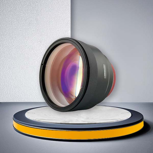
| TELECENTRIC 355nm Fuced Silica | |||||||||
| Model | Input Aperture (mm) | Scan Field (mm) | Focal Length (mm) | Working Distance (mm) | Scan Angle (º) | Spot Size (µm) | Φ Diameter (mm) | Max. Impact Angle (º) | Mount Thread |
| f-30T-355 | 10 | Φ 8.5 (8 x 8) | 30 | 35.347 | ±10.5º | 1.95 | 47.4 | 47.4 | M39 × 1 |
| f-32T-355B | 10 | Φ 8.5 (1 x 1) | 32 | 26.34 | ±7.6º | 3.2 | 90 | 90 | M85 × 1 |
| f-60T-355 | 10 | Φ 31 (22 × 22) | 60 | 73.65 | ±16º | 11.5 | 90 | 90 | M85 × 1 |
| f-65T-355 | 10 | Φ 21.2 (15 x 15) | 65 | 81.106 | ±9.4º | 4.2 | 94 | 94 | M85 × 1 |
| f-70T-355 | 10 | Φ 40 (28 x 28) | 73.9 | 91.35 | ±16º | 4.5 | 90 | 90 | M85 × 1 |
| f-100T-355 | 14 | Φ71 (50.8 × 50.8) | 100 | 107.68 | ±20.4 º | 6.69 | 120 | 120 | M85 × 1 |
| f-100T-14-355B | 14 | Φ 70.7 (50 x 50) beam=14mm | 100 | 135.475 | ±21º | 5 | 120 | 120 | M85 × 1 |
| f-103T-355 | 12 | Φ 10% (51 × 51) | 103 | 136.13 | ±20.4º | 5.58 | 100 | 100 | M85 × 1 |
| f-110T-355 | 8 | Φ 92 (65 × 65) | 110 | 153.88 | ±24º | 8.9 | 120 | 120 | M85 × 1 |
| f-120T-355 | 10 | Φ 92 (65 × 65) | 120 | 149.107 | ±22.5º | 8 | 118 | 118 | M85 × 1 |
| f-130T-355 | 10 | Φ 85 (60 × 60) | 130 | 159.92 | ±19º | 8.45 | 120 | 120 | M85 × 1 |
| f-167T-10-355 | 10 | Φ 127 (90 × 90) | 167 | 211.25 | ±24º | 10.8 | 130 | 130 | M85 × 1 |
| f-167T-14-355 | 14 | Φ 99 (70 × 70) | 167 | 234.52 | ±18º | 7.8 | 140 | 140 | M85 × 1 |
| F-167T-14-355B | 14 | Φ 127 (90 × 90) | 166.57 | 229.163 | ±22º | 7.7 | 159 | 159 | M85 × 1 |
| f-175T-355 | 10 | Φ 142 (101 × 101) | 175 | 247.487 | ±24º | 11.8 | 140 | 140 | M85 × 1 |
| f-295T-14-355 | 14 | Φ244 (110% x 110%) | 295 | 426.75 | ±23.7º | 13 | 280 | 280 | M85 × 1 |
| f-330T-355 | 14 | Φ 245 (173 × 173) | 330 | 581.581 | ±20º | 15.3 | 270 | 270 | M85 × 1 |
| TELECENTRIC 532nm Fuced Silica | |||||||||
| Model | Input Aperture (mm) | Scan Field (mm) | Focal Length (mm) | Working Distance (mm) | Scan Angle (º) | Spot Size (µm) | Φ Diameter (mm) | Max. Impact Angle (º) | Mount Thread |
| f-63T-510-550 | 10 | Φ 33 (23 × 23) | 63 | 82.1 | ±16° | 6.2 | 90 | 1 | M85 × 1 |
| f-88T-14-510-550 | 14 | Φ 52 (37 × 37) | 88 | 100.63 | ±17° | 10 | 120 | 1.9 | M85 × 1 |
| f-100T-510-550 | 10 | Φ 76 (54 × 54) | 100 | 142.2 | ±20.7° | 13.5 | 120 | 0.38 | M85 × 1 |
| f-100T-14-510-550 | 14 | Φ 70.7 (50 × 50) | 100 | 135.402 | ±21° | 7 | 120 | 1.3 | M85 × 1 |
| F-167T-14-510-550 | 14 | Φ 127 (90 × 90) | 167 | 232.23 | ±21° | 11.61 | 140 | 3 | M85 × 1 |
| TELECENTRIC 532nm Optical Glass | |||||||||
| Model | Input Aperture (mm) | Scan Field (mm) | Focal Length (mm) | Working Distance (mm) | Scan Angle (º) | Spot Size (µm) | Φ Diameter (mm) | Max. Impact Angle (º) | Mount Thread |
| f-100T-532 | 15 | Φ 71 (50 × 50) | 100 | 125.04 | ±21.5° | 6.5 | 120 | 3.2 | M85 × 1 |
| f-110T-532 | 15 | Φ 83 (60 × 60) | 110 | 132.94 | ±21.5° | 7.2 | 120 | 3.2 | M85 × 1 |
| f-170T-532 | 14 | Φ 129 (91 × 91) | 170 | 214.66 | ±21.8° | 11.8 | 140 | 3 | M85 × 1 |
| f-170T-20-532 | 20 | Φ 141 (100 × 100) | 170 | 204.788 | ±24° | 8.53 | 164 | 4 | M102 × 1 |
| TELECENTRIC 1064nm Fuced Silica | |||||||||
| Model | Input Aperture (mm) | Scan Field (mm) | Focal Length (mm) | Working Distance (mm) | Scan Angle (º) | Spot Size (µm) | Φ Diameter (mm) | Max. Impact Angle (º) | Mount Thread |
| f-32T-1030-1080 | 10 | Φ 8.5 (6 × 6) | 32 | 31.79 | ±7.6° | 6.2 | 90 | 1.4 | M85 × 1 |
| f-65T-1030-1080 | 10 | Φ 36 (26 × 26) | 65 | 80.99 | ±16° | 12.65 | 90 | 0.58 | M85 × 1 |
| f-88T-20-1030-1080 | 20 | Φ 28.28 (20 × 20) | 88 | 120.51 | ±9.5° | 8.78 | 120 | 1.3 | M85 × 1 |
| f-90T-20-1030-1080 | 20 | Φ 54 (38 × 38) | 90 | 101.323 | ±17° | 35 | 120 | 1.9 | M85 × 1 |
| f-100T-1030-1080 | 14 | Φ 76 (54 × 54) | 100 | 142.73 | ±20.7° | 13.5 | 120 | 0.59 | M85 × 1 |
| f-100T-1030-1080 | 14 | Φ 76 (54 × 54) | 100 | 142.73 | ±20.7° | 13.5 | 135 | 0.59 | M85 × 1 |
| f-100T-14-1030-1080 | 14 | Φ 72 (51 × 51) | 100 | 130.44 | ±20° | 13.9 | 120 | 0.5 | M85 × 1 |
| f-120T-1030-1080 | 10 | Φ 98 (70 × 70) | 120 | 168.59 | ±24° | 23.5 | 120 | 3 | M85 × 1 |
| f-125T-14-1030-1080 | 14 | Φ 77.7 (55 × 55) | 125 | 153.27 | ±16.5° | 17.39 | 112 | 2 | M85 × 1 |
| f-125T-20-1030-1080 | 20 | Φ 70.7 (50 × 50) | 125 | 153.27 | ±18° | 12.17 | 112 | 1.8 | M85 × 1 |
| f-167T-1030-1080 | 14 | Φ 120 (85 × 85) | 167 | 215.5 | ±20.3° | 17 | 140 | 3.69 | M85 × 1 |
| f-200T-14-1030-1080 | 14 | Φ 141 (100×100) | 200 | 296.954 | ±20° | 27.82 | 173 | 2 | M85 × 1 |
| f-254T-14-1030-1080 | 14 | Φ155.5(110×110) | 254 | 376.53 | ±18° | 35.3 | 126 | 5 | M85 × 1 |
| TELECENTRIC 1064nm Optical Glass | |||||||||
| Model | Input Aperture (mm) | Scan Field (mm) | Focal Length (mm) | Working Distance (mm) | Scan Angle (º) | Spot Size (µm) | Φ Diameter (mm) | Max. Impact Angle (º) | Mount Thread |
| f-100T-1064 | 15 | Φ 77 (55 × 55) | 100 | 122.8 | ±22° | 13 | 120 | 2.1 | M85 × 1 |
| f-125T-1064 | 20 | Φ 109 (66 × 66) | 125 | 139.58 | ±21.5° | 12 | 120 | 3 | M85 × 1 |
| f-167T-1064 | 20 | Φ 125 (90 × 90) | 167 | 216.23 | ±21° | 16.5 | 140 | 4.4 | M85 × 1 |
| F-170T-30-1064 | 30 | Φ 120 (88 × 88) | 170 | 209.61 | ±21° | 11.1 | 140 | 4.4 | M102 × 1; M112 |
| f-183T-20-1064 | 20 | Φ 70.7 (50×50) | 183 | 219.63 | ±11.5° | 17.82 | 113 | 0.8 | M85 × 1 |
| f-210T-30-1064-M95 | 30 | Φ 161 (115×115) | 210 | 279.63 | ±22° | 13.69 | 188 | 3.3 | M95×1 |
| f-210T-30-1064-M102 | 30 | Φ 154(108×108) | 210 | 279.63 | ±21° | 13.69 | 188 | 3.3 | M102×1 |
| f-211T-10-1064-M85 | 10 | Φ 147(104×104) | 211 | 279.63 | ±20° | 41.1 | 150 | 4.4 | M85 × 1 |
| f-315T-14-1064B | 14 | Φ 269(190×190) | 315 | 432.072 | ±24.5° | 43.8 | 270 | 2.3 | M85 × 1 |
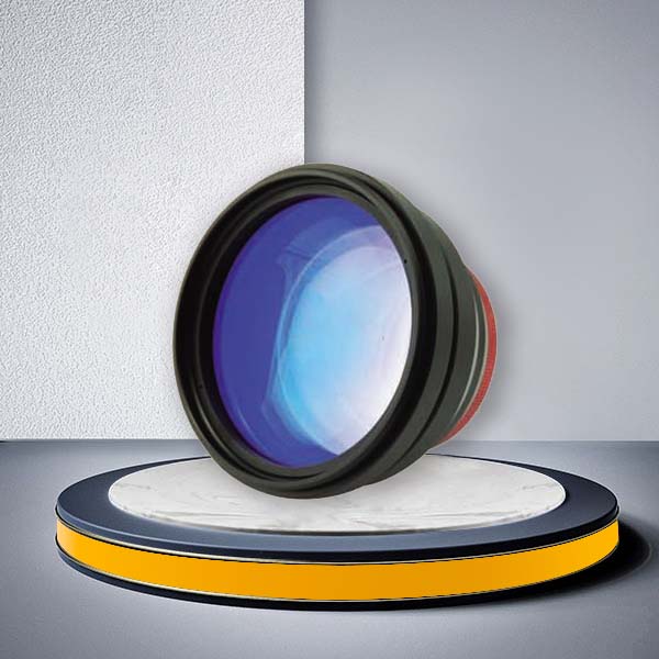
Telecentric F-Theta Lens Manufacturer for 355nm, 532nm & 1064nm Laser Systems
JCZ provides telecentric F-theta lenses for precision laser scanning systems operating at 355 nm, 532 nm and 1064 nm / 1030–1080 nm. Multiple configurations are available with different input apertures, scan fields, focal lengths, working distances, spot sizes and mounting threads, allowing laser machine manufacturers and system integrators to match the lens to the complete optical system rather than selecting by focal length alone.
Unlike a standard F-theta scan lens, a telecentric F-theta lens is designed to keep the focused beam closer to perpendicular to the working plane across the scan field. This makes it especially suitable for precision drilling, micromachining, cutting and applications where beam incidence angle and processing consistency across the field are important.
JCZ currently offers both fused silica and optical glass telecentric F-theta lens configurations for different laser wavelengths and processing requirements.
Why Choose a Telecentric F-Theta Lens?
A standard F-theta lens provides a flat scanning field, but the beam becomes increasingly inclined as it moves toward the edge of the working area.
A telecentric F-theta lens is designed to reduce this variation in beam incidence angle.
This can provide several advantages:
- More perpendicular beam incidence – Helps control drilling and cutting geometry across the entire processing field.
- Improved spot consistency – Supports more uniform laser processing from the center to the edge of the scan field.
- Better hole geometry – Useful for micro-hole drilling where sidewall angle is important.
- Higher processing consistency – Helps reduce differences caused by beam inclination at different scan positions.
- Suitable for precision applications – Commonly used in electronics, semiconductor, display, PCB and micro-processing systems.
JCZ’s current product page states that the impact angle is controlled so that the output beam remains nearly perpendicular to the working plane, improving focal spot roundness, XY uniformity and Z-direction perpendicularity.
Telecentric F-Theta Lens vs Standard F-Theta Lens
| Selection Factor | Standard F-Theta Lens | Telecentric F-Theta Lens |
|---|---|---|
| Flat focal plane | Yes | Yes |
| Beam incidence at field edge | More inclined | Designed to remain closer to perpendicular |
| General laser marking | Strong fit | Possible, but may be unnecessary |
| Precision micro-drilling | Application dependent | Strong fit |
| Vertical hole requirement | Limited by beam angle | Better suited |
| Precision cutting | Suitable for many applications | Preferred where angle consistency matters |
| Spot consistency across field | Design dependent | Greater emphasis on field consistency |
| Optical diameter | Usually smaller | Often larger |
| Cost | Generally lower | Generally higher |
| System selection complexity | Lower | Requires closer scanner/lens matching |
Choose a standard F-theta lens when the application is mainly conventional flat-surface marking, engraving or general industrial processing.
Choose a telecentric F-theta lens when beam incidence angle, verticality, spot uniformity or edge-of-field processing consistency directly affects the process result.
Choose a Telecentric F-Theta Lens by Laser Wavelength
Wavelength compatibility should be confirmed before comparing focal length or scan field.
JCZ currently lists configurations for the following laser wavelengths.
| Wavelength | Available Material | Current Published Configuration | Typical Direction |
|---|---|---|---|
| 355 nm | Fused Silica | Multiple apertures, fields and focal lengths | UV precision processing, PCB, electronics, glass, micro-processing |
| 532 nm | Fused Silica / Optical Glass | Multiple telecentric configurations | Green laser precision processing, glass, semiconductor, electronics |
| 1030–1080 / 1064 nm | Fused Silica / Optical Glass | Broadest current configuration range | Fiber/IR laser marking, drilling, engraving and precision processing |
How to Select the Right Telecentric F-Theta Lens
A telecentric scan lens should not be selected simply by choosing the largest available scan field.
Use the following parameters together.
| Parameter | Why It Matters |
|---|---|
| Laser Wavelength | Determines substrate and AR coating requirements |
| Input Beam Diameter | Must match the usable optical aperture |
| Galvo Aperture | Must be compatible with the lens input beam requirement |
| Scan Field | Defines the usable processing area |
| Focal Length | Influences field size, working distance and focused spot |
| Working Distance | Must fit the mechanical design of the laser machine |
| Spot Size | Affects feature size and energy density |
| Scan Angle | Must match the galvo and optical design |
| Telecentricity | Determines how closely the beam remains perpendicular across the field |
| Lens Diameter | Affects machine space and mechanical integration |
| Mount Thread | Must match the scanner/lens mount |
| Laser Power | Determines thermal and coating requirements |
A larger scan field normally requires trade-offs in lens diameter, focal length, spot size or optical complexity.
For precision laser systems, the lens should therefore be selected together with the galvo scanner rather than treated as an independent component.
Understanding Telecentricity and Impact Angle
Telecentricity is one of the most important specifications when evaluating a telecentric F-theta lens.
The telecentricity error describes the maximum angular deviation between the focused laser beam and a line perpendicular to the workpiece.
A lower deviation can be beneficial for applications such as:
- Micro-hole drilling.
- Precision via drilling.
- Vertical cutting.
- Semiconductor processing.
- Display processing.
- Micro-structuring.
Sill Optics also notes that telecentricity is affected by the complete scanner/lens geometry. Mirror spacing and input beam diameter can change scan field, spot diameter and telecentricity performance, meaning a lens specification should not always be evaluated independently from the scanner.
Scan Field, Spot Size and Working Distance
Three parameters should be considered together when selecting a telecentric F-theta lens.
Scan Field
The scan field determines how large an area the galvo system can process without mechanically moving the workpiece.
Increasing the field generally requires a longer focal length or larger optical system.
Spot Size
Spot size affects:
- Minimum achievable feature size.
- Processing resolution.
- Laser energy density.
- Cutting or drilling performance.
A smaller published spot size does not automatically mean a better lens. Spot size also depends on wavelength, input beam diameter, beam quality and focal length.
Working Distance
Working distance affects:
- Machine mechanical layout.
- Workpiece clearance.
- Fixture design.
- Fume and debris protection.
- Vision or auxiliary-module installation.
The correct lens is therefore the configuration that balances field size, spot size and working distance for the specific machine.
Fused Silica vs Optical Glass Telecentric F-Theta Lens
JCZ currently provides both fused silica and optical glass configurations for several wavelength ranges.
| Factor | Fused Silica | Optical Glass |
|---|---|---|
| UV transmission | Strong advantage | Material dependent |
| Thermal stability | Generally higher | Application dependent |
| High laser power | Often preferred | Depends on coating and power |
| Ultrafast laser systems | Often preferred | Requires verification |
| Material cost | Higher | Often more economical |
| General industrial laser systems | Suitable | Suitable |
| High precision thermal stability | Stronger option | Depends on design |
Fused silica should be considered when UV transmission, thermal stability or high-power operation is important.
Optical glass can be a practical option when the wavelength, laser power and required optical performance allow it.
Telecentric F-Theta Lens Applications
PCB and Electronics Processing
Telecentric lenses are suitable for applications where small feature size and controlled drilling geometry are important, including:
- PCB via drilling.
- FPC processing.
- Electronic component marking.
- Micro-hole processing.
- Fine laser structuring.
Semiconductor and Display Processing
The telecentric optical design can help maintain more consistent beam geometry across the scan field for:
- Wafer processing.
- Semiconductor packaging.
- Display cutting.
- OLED processing.
- ITO structuring.
- Precision glass processing.
Precision Laser Drilling
A telecentric F-theta lens is particularly useful when the laser hole should remain closer to vertical at different positions in the scan field.
Typical applications include:
- Micro vias.
- Precision holes.
- Thin-film drilling.
- Electronic substrates.
- Glass and ceramic drilling.
Precision Laser Cutting
Telecentric optics can be considered when edge-of-field beam angle affects cut quality.
Typical applications include:
- Display glass.
- Thin electronic materials.
- Semiconductor substrates.
- Precision components.
- Thin-film materials.
High-Precision Laser Marking
Telecentric designs can also be used when marking accuracy and spot geometry must remain consistent across a relatively small processing field.
Match the Lens with Your Galvo Scanner
A telecentric F-theta lens and galvo scanner should be treated as one optical system.
Before selecting a lens, confirm:
- Galvo scanner aperture.
- Laser beam diameter.
- Distance between X and Y galvo mirrors.
- Scanner-to-lens geometry.
- Maximum scan angle.
- Laser wavelength.
- Required processing field.
- Required working distance.
- Target spot size.
- Mounting interface.
Sill Optics notes that changing scanner mirror spacing or input beam diameter can alter scan field, spot diameter and telecentricity even when the lens itself remains unchanged.
JCZ also supplies 2D galvo scanners for industrial laser systems.
Custom Telecentric F-Theta Lens Options
JCZ provides a broad range of standard telecentric F-theta lens configurations. For OEM laser machines or applications that cannot be covered by the published models, customized optical configurations may also be required.
Potential customization requirements include:
- Custom laser wavelength.
- Custom wavelength bandwidth.
- Custom scan field.
- Custom focal length.
- Custom working distance.
- Custom input aperture.
- Custom spot-size target.
- Custom telecentricity requirement.
- Custom AR coating.
- Custom optical substrate.
- Custom mounting thread.
- Custom mechanical housing.
- Custom scanner/lens integration.
- OEM optical design.
How to Specify a Telecentric F-Theta Lens for Quotation
To recommend a suitable lens, provide the following information:
- Laser wavelength.
- Laser type and model.
- Average and peak laser power.
- Beam diameter entering the galvo.
- Beam quality M², if available.
- Galvo scanner model.
- Galvo aperture.
- Required scan field.
- Required working distance.
- Required spot size or minimum feature size.
- Maximum acceptable beam-incidence angle.
- Material being processed.
- Laser process: marking, drilling, cutting or micromachining.
- Mounting thread or mechanical drawing.
- Expected annual quantity.
If you are designing a complete laser system, JCZ can also help evaluate the relationship between the controller, galvo scanner and laser optics.
Frequently Asked Questions
What is the difference between a standard F-theta lens and a telecentric F-theta lens?
A standard F-theta lens focuses the laser onto a flat field, but the beam normally becomes more inclined toward the edge of the scanning area. A telecentric lens is designed to reduce this change in beam incidence angle.
Which wavelengths are available?
JCZ currently lists telecentric lens configurations for 355 nm, 532 nm and 1030–1080 / 1064 nm laser systems.
How do I choose the correct focal length?
Focal length should be selected together with required scan field, spot size, input beam diameter and working distance. A longer focal length generally provides a larger field and longer working distance but can also increase focused spot size.
How do I select the scan field?
Start from the maximum required processing area, then confirm whether the corresponding lens also provides an acceptable spot size, working distance, telecentricity and physical diameter.
Does a smaller spot size always mean better performance?
No. Spot size depends on wavelength, focal length, beam diameter and beam quality. The correct spot size should match the required feature size and laser energy density.
Should I choose fused silica or optical glass?
Fused silica is generally preferred when UV transmission, high laser power or thermal stability is important. Optical glass can provide a practical solution for many industrial laser systems when the wavelength and power are suitable.
Can the telecentric lens work with any galvo scanner?
Not automatically. Galvo aperture, mirror spacing, scan angle, input beam diameter and mounting geometry can affect field size, spot quality and telecentricity. The scanner and lens should be evaluated as one optical system.
What information should I provide for a custom lens?
Provide the laser wavelength, beam diameter, galvo model, required scan field, working distance, target spot size, processing application, laser power and mechanical interface requirements.
Find the Right Telecentric F-Theta Lens for Your Laser System
Choosing the right telecentric F-theta lens manufacturer involves more than comparing focal length and scan field.
The lens must match the laser wavelength, beam diameter, galvo scanner, processing field, working distance, spot-size requirement and telecentricity requirement as one optical system.

Send JCZ your laser source, galvo scanner and application specifications to identify a suitable 355 nm, 532 nm or 1064 nm telecentric F-theta lens configuration.