How to Size an Enclosed Laser Marker for Parts, Fixtures, and Automation
Choosing an enclosed laser marker often gets boiled down to the power of the laser source or the marking speed. While both matter, neither matters if the part cannot physically fit inside the machine—or if the fixture and automation hardware you need to attach will not clear the safety door. Engineers and buyers in manufacturing environments learn this the hard way: a machine that looked spacious in a brochure becomes a bottleneck on the shop floor because nobody measured the part at its worst orientation, added the clamp, and left room for a robotic gripper. This article provides a methodical, data‑based approach to sizing an enclosed laser marker from the part outward, factoring in fixturing, automation interfaces, and safety regulations that dictate the final footprint. It is written for manufacturing engineers, production managers, and system integrators who are done with guesswork.
Why enclosure sizing is more than a “box” problem
An enclosed laser marker is classified as a Class 1 laser product when the access panels are closed. That classification is not a convenience—it is a legal requirement in jurisdictions that adopt IEC 60825‑1 and ANSI Z136.1. To maintain Class 1 during normal operation, every access opening, light curtain gap, and exhaust vent must be designed so that the accessible radiation is below the Maximum Permissible Exposure (MPE). The enclosure’s dimensions therefore start with a safety envelope, not with a convenient sheet‑metal frame.
At the same time, the physical volume inside must house the scanning head, the working plane, the part, its fixture, and often a pneumatic or electric axis that brings the part in and out. Many integrators overlook the depth required behind the scanning head for cabling and the service loop of the galvo cables. A typical compact desktop enclosure might offer an internal working volume of 300 × 300 × 200 mm (L × W × H), while a larger freestanding system for automotive parts can reach 1000 × 800 × 600 mm. These ranges are based on dozens of machine specifications from established laser integrators; the exact numbers vary by manufacturer. The key is to treat the enclosure as the interface between your production line and the laser process—and size it accordingly.
Define the worst‑case part envelope
The first data point you need is not the nominal part size but the extreme envelope the laser will ever see during production. Start with the part’s maximum dimensions after taking into account all angular positions. A connecting rod that is 180 mm long in plan view becomes 230 mm long when tilted 30° in a rotary fixture. Add to that the fixture baseplate thickness, clamping arm travel, and any sensor brackets. Then double the clearance from the part to the enclosure walls: at least 50 mm on all sides is a common minimum to prevent scattered laser radiation from reflecting off a wall back onto the optics, and to ensure airflow for fume extraction clears the marking field. In practice, a fixture‑heavy setup can easily require an internal width 150 mm larger than the raw part width.
| Part Type | Typical Raw Part Size (L×W×H, mm) | Minimum Recommended Enclosure Interior (L×W×H, mm) | |———————–|————————————|—————————————————–| | Small electronic tags | 30×10×2 | 200×200×150 | | Automotive badge | 120×40×5 | 300×250×150 | | Hydraulic valve body | 250×150×80 | 500×350×250 | | Casting with fixture | 350×200×100 | 600×450×300 |
These recommendations are derived from typical galvo‑based marker packaging geometries and assume a fixed table configuration. When a rotary axis or multi‑station indexer is added, the height column often drives the decision: a 100 mm tall part on a rotary that lifts it 80 mm above the base needs at least 200 mm of clear Z height under the galvo head.
Align the galvo scan field with what you really need
The scan field of a galvo scanner is usually given as a square dimension at a specific focal length—110×110 mm, 175×175 mm, 300×300 mm, and so on. However, the usable field where distortion and spot‑size variation stay within an acceptable range is typically 80–90% of that nominal area. For example, a 175 mm field lens yields a practical marking area of about 150 × 150 mm for most applications. If you need to mark a pattern that spans 200 mm across a part, a single 175 mm field will not cut it unless you use stitching or a larger lens. Larger scan fields come with a trade‑off: the spot size increases roughly linearly, which reduces energy density and can slow deep engraving.
JCZ’s control hardware allows system builders to set the marking field precisely in software. When a machine builder integrates a Laser Software tool, the work area is defined within the EZCAD platform, letting the operator map the physical field size to the design canvas. For machines that must handle parts longer than the galvo field, Ezcad2 Software supports dual‑axis splicing—two or more scan fields are joined with motorized stage movement, enabling uninterrupted marking over lengths of 500 mm or more. This capability directly affects enclosure sizing: you must extend the length to accommodate the stage travel, plus cable management, without breaking the Class 1 barrier.
Accommodate automation interfaces: doors, tunnels, and safety circuits
Enclosed markers meant for automated lines are rarely simple boxes with a manual door. They have openings for conveyor tunnels, robot access windows, light curtains, or pressure‑sensitive mats. Each opening changes the safety architecture. According to ISO 13855, the minimum distance from a light curtain to the hazard zone must be calculated based on the stopping time of the machine and the approach speed—typically 2000 mm/s for a body, 1600 mm/s for limbs. This safety distance can push the enclosure physically longer. A robot that reaches inside through an automated door will require that the door opening be guarded by an interlock meeting at least Performance Level c (ISO 13849‑1) or higher depending on the risk assessment.
For flying‑marking systems where parts move continuously on a conveyor, the enclosure needs entrance and exit tunnels with baffles or laser‑safe fabric that maintain Class 1 without impeding product flow. The tunnel length is often three times the cross‑sectional opening to ensure enough attenuation. In such setups, Ezcad3 Software is frequently chosen for its faster data processing and the ability to handle high‑precision timing triggers from conveyor encoders. The software architecture slices the marking file into segments and synchronizes each segment with the encoder pulses, which typically run at 10 kHz resolution—a common automated line requirement—allowing marking on‑the‑fly at speeds up to 60 m/min. The enclosure’s length must leave room for the part to enter, be marked over a defined zone, and exit while still inside the guarded volume.
The software‑size relationship many engineers miss
Machine footprint decisions often happen before anyone looks at the software, but software can dramatically change how much physical travel you need. If a marking layout can be split into multiple steps with an XY table repositioning the part, a smaller galvo field and thus a narrower enclosure become feasible. EZCAD’s array and split functions let you program marker‑controlled stages that move between segments, reducing the need for a single enormous scan lens. Without this planning, teams frequently over‑specify the enclosure width to fit a larger galvo, adding cost and floor space unnecessarily.
On the other side, underestimating the role of software leads to machines that cannot mark the full part without time‑consuming manual repositioning. With Ezcad2 Software, the “Flying Marking” module and the multi‑file batch processing are standard, so the same enclosure can serve both standalone and inline configurations if the offsets are saved in the job file. When you evaluate a machine, ask the builder to show a virtual layout of the part with the software’s simulation tool—this will reveal whether the clearance you assumed actually works when the galvo head tilts to the field edge.
Safety regulations that impose dimensional constraints
Laser enclosure design is not a voluntary exercise. IEC 60825‑1 and the corresponding FDA CDRH requirements in the U.S. mandate specific interlocks, viewing window attenuation, and warning labels. The viewing window is a common dimensional trap: an operator or camera must be able to see the entire marking field without moving, but the window’s optical density must be high enough to block residual radiation. A typical ytterbium‑fiber laser operating at 1064 nm requires an OD 4+ window at that wavelength, which usually means an acrylic or polycarbonate panel 3–5 mm thick with a specific dye. That thickness eats into the usable headroom. Furthermore, the window must not be so large that a person can reach through if broken; this is why larger viewports are often subdivided by ribs.
For automated systems, the safety circuit must prevent the laser emission when a door is open or a light curtain is interrupted. The architecture commonly requires a dual‑channel safety relay and feedback monitoring, as described in ISO 13849‑1 Category 3. Each interlock switch on a door typically has a certified lifespan of 1 million operations, after which it must be replaced to maintain the safety integrity level. Choosing a compact machine with a tiny service door might save floor space initially but force frequent switch replacements in high‑throughput lines. The maintenance clearance behind the hinged door must leave enough room for a technician to swing it open fully—often an extra 900 mm of aisle space beyond the enclosure footprint.
Four engineering pitfalls and how to avoid them
Assuming the galvo mounting height is free. Every galvo head has a recommended working distance from the bottom of the housing to the focal plane, typically 100–200 mm depending on the lens. If the part and fixture stack up to 180 mm and you select a lens with an 85 mm working distance, you simply cannot focus. Always get the optical layout drawing and add 20 mm of Z‑axis adjustment margin.
Ignoring exhaust duct volume. Laser marking of plastics or coated metals produces fumes that must be extracted at a velocity of at least 0.5 m/s across the marking plane, as recommended by industrial hygiene guidance. A 150 mm diameter duct flange and the associated hose can demand an extra 300 mm of rear clearance beyond the enclosure’s back panel. Compact “desktop” systems often fail here when integrated into a cell.
Not testing the automation grip clearance. A pneumatic gripper that grasps the part from above requires vertical room above the part equal to the gripper stroke plus safety margin, often 80‑120 mm. Check that this space does not collide with the galvo head or the fume extraction nozzle during the “tool up” position.
Underestimating commissioning time due to software setup. A machine delivered without a pre‑configured EZCAD work area library forces the integrator to map axes and toggle safety zones from scratch. Pre‑load the job with the correct field size, stage limits, and interlocks, which the Laser Software developer ecosystem supports through the EZCAD SDK. This can cut commissioning from days to hours.
Common questions from manufacturing teams
Does every enclosed laser marker need a fully welded steel enclosure?
No. Many smaller systems use formed aluminum and polycarbonate that still meet Class 1 when tested with the specific laser source. The material choice depends more on the laser wavelength and structural stiffness than on the welding process. However, thin‑gauge metals can leak radiation at seams if not properly overlapped, so continuous welding or gasketed joints are common. The key is that the enclosure passes a measurement per IEC 60825‑1 Clause 4, not a prescriptive material list.
Can I add automation to an existing benchtop enclosed marker?
It is possible but often economically messy. Retrofitting a conveyor pass‑through tunnel to a benchtop system requires recertifying the safety circuit and likely upgrading the door interlock from a single‑channel to a dual‑channel system. The internal volume might not accommodate a lift‑and‑locate mechanism. If you know automation is in your 12‑month roadmap, spec the enclosure with automation cutouts and an extra 200 mm of tunnel length from the start. The marginal cost increase is far lower than replacing the entire station later.
How do I validate that an enclosure will not distort over time?
For large sheet‑metal enclosures (over 800 mm span), thermal warping from internal heat sources can change the door gaps. A standard practice is to run the system at full laser power for temperature‑soak testing and then measure gaps with a feeler gauge; any gap above 0.5 mm on a laser‑accessible seam is a potential leak path. Good integrators include welded square‑tube frames inside the sheet‑metal skins to hold flatness within 0.3 mm across a 1 m panel.
Next steps toward a correctly sized system
Sizing an enclosed laser marker is not a single‑number exercise. It starts with the part at its largest real‑world orientation, adds the fixture and gripper stroke, then applies safety margins that keep the system compliant with IEC and ISO standards. An effective decision cycle involves obtaining 3D layout drawings from the machine builder, feeding the actual part and fixture CAD into the Ezcad3 Software simulation view, and confirming the critical dimensions before the steel is cut.
Once the footprint is defined, validate the selection with a sample run that includes the most awkward loading scenario—manual or robotic. Demand a thermal and fume extraction test run at production cadence. Finally, ask the integrator to provide a signed risk assessment per ISO 12100, which will list the safety functions and the verified performance levels for each interlock and light curtain. With these concrete steps, how to size an enclosed laser marker for parts, fixtures, and automation becomes a reproducible engineering process, not a gamble.
OFFICIAL DRIVER UPDATE NOTICE

Top Factors That Affect Marking Quality in Handheld Fiber Laser Systems

Meet JCZ at Laser World of Photonics India 2026 in Bengaluru
Laser Marking Fabric with Portable Laser Engraver: Advanced UV Laser Marking Solutions for Modern Manufacturing
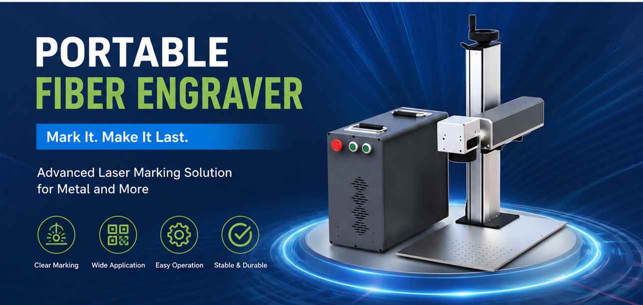
Laser Machine for Marking: The Ultimate Guide to Portable Fiber Engravers & MOPA Color Laser Marking

Laser Cleaning Machine for Wood: The Ultimate Guide to Safe, Precise & Eco-Friendly Wood Surface Cleaning