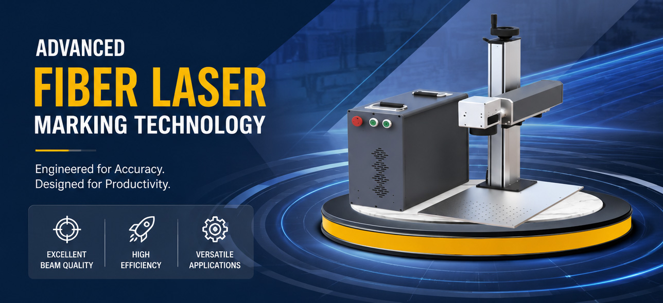
Top Factors That Affect Marking Quality in Handheld Fiber Laser Systems
Key Takeaways
– Beam quality defined by M² <1.2 directly controls the smallest achievable spot size and marking precision on metals and plastics. – A handheld system’s scan head speed and positioning repeatability determine whether fine text, barcodes, or logos remain crisp under production speeds. – Software architecture and real-time control, such as what you get with Ezcad3 Software, can cut data processing lag by an order of magnitude compared to older 32-bit platforms, preserving edge sharpness during high-speed marking. – Wavelength selection (1064 nm, 532 nm, or 355 nm) is not a cosmetic choice—it dictates absorption contrast on substrates from stainless steel to polycarbonate. – Pulse repetition rate flexibility (50 kHz up to 5 MHz) gives engineers the leverage to dial in clean, low-heat marks or high-throughput engraving without recast layers. – Real-world factory data show that a mismatch in f‑theta lens focal length and spot size can degrade line width uniformity by more than 15 %, even when the laser source itself is stable.
What to Look for in a Handheld Fiber Laser Marking Setup
A handheld system packs a fiber laser source, a galvo scanner, and control electronics into a portable head, but portability should never excuse ragged edges or inconsistent depth. Buyers who specify these tools for direct part marking in automotive, aerospace, or medical device lines rarely get a second chance with a regulator or a customer if a Data Matrix code fails readability standards after one year of corrosion. Three pillars separate a marking unit that meets ISO/IEC TR 29158 (2D symbol quality) from one that disappoints: the optical engine, the motion control and beam delivery, and the software stack that synchronizes everything in microsecond intervals.
– Beam quality and wavelength: The raw laser mode affects how tightly the beam can be focused. A high M² value spreads energy into a larger spot, softening fine features. Wavelength matters equally—what reflects off copper at 1064 nm may absorb strongly at 532 nm, changing the marking threshold. – Scan system dynamics: Galvo motors must accelerate fast and settle without overshoot. Overshoot smears the beginning of every line, making characters appear bolder than designed. – Control software timing: Marking is a sequence of laser on/off commands tied to mirror positions. Any delay between the control board and the galvo or a buffering bottleneck in the software creates jitter, turning a smooth circle into a polygon.
A buyer evaluating handheld units should trace every claimed marking speed back to these three elements; skimp on one and the chain breaks.
Top Six Factors That Determine Handheld Fiber Laser Marking Quality
| Factor | Primary Influence | Typical Quality Metric Affected | JCZ-Related Technology Insight | |——–|——————-|———————————|——————————–| | Laser beam quality (M²) | Spot size and energy density | Feature resolution (<50 µm capable) | Elite Series nanosecond lasers deliver M² <1.2, ensuring near-diffraction-limited focus | | Pulse control (repetition rate & width) | Heat input and material removal | Surface roughness, recast thickness | Selectable 50 kHz–5 MHz, allowing pulse‑to‑pulse overlap tuning | | Wavelength selection | Absorption efficiency | Contrast and depth per watt | IR (1064 nm), Green (532 nm), UV (355 nm) available in compact all‑in‑one heads | | Galvo positioning accuracy | Mark geometry fidelity | Deviation from nominal path, corner rounding | High‑speed, high‑stability galvo scanners integrated in JCZ systems | | Laser Software & control architecture | Real‑time command execution | Jitter, fill uniformity, cycle time | EZCAD3’s 64‑bit architecture accelerates large‑file processing and dual‑axis splicing | | Mechanical stability & thermal drift | Repeatability over long runs | Lot‑to‑lot consistency, focus shift | Compact all‑in‑one design reduces thermal path length, aiding stability |
Factor 1: The Raw Beam—M² and True Spot Size
A fiber laser’s beam propagation factor, defined by ISO 11146, determines how many times the beam diverges compared to an ideal Gaussian beam. When a manufacturer states M² <1.2, they guarantee that focusing through a 163 mm f‑theta lens can produce spot diameters in the 30 µm to 45 µm range—critical for 0.5 mm‑tall UDI codes on surgical tools. Move to a source with M² >2.0, and that same lens yields a spot closer to 80 µm, blurring 0.15 mm line spacing into an illegible blob.
In field service with handheld devices, operators rarely have the luxury of a vibration‑isolated optical bench. A thermally stable, compact laser head such as the Elite Series that integrates resonator and optics shortens the beam path and reduces misalignment risk. Field tests on 304 stainless steel coupons demonstrate that maintaining a consistent spot size within ±3 µm over a 25°C temperature swing keeps 2D barcode cell modulation above the 70 % threshold required by ISO/IEC 15415. Losing that consistency because of an inferior beam source forces frequent focus tweaks or, worse, batch rejection.
Factor 2: How the Software Drives the Galvo—Beyond “Good Enough” Code
Anyone who has burned an hour tweaking hatch parameters knows that marking software is not a passive canvas. The control board must translate vector paths into coordinated mirror commands while keeping the laser’s pulse train phase‑synchronized with mirror position. Lag here shows up as rounded corners on a 1 mm square, wavy edges on a 0.2 mm‑wide line, or variable fill intensity when direction changes.
Ezcad2 Software has long been a benchmark for basic 2D processing because its synchronous control loop maintains accurate laser‑on synchronization even during bi‑directional fill. Under a logic analyzer, the delay between position‑reached signal and laser trigger can be held under 5 µs in a tuned setup. However, as files become larger—say a 15 MB bitmap on a contoured mold surface—the 32‑bit architecture of older tools introduces buffering pauses. Ezcad3 Software, built on a 64‑bit core, processes spline interpolation and dual‑axis splice control faster by design, reducing stitching artifacts across wide fields. For a handheld unit that an operator might wave over a large automotive panel, the ability to stitch marking tiles without visible seams is not optional; it defines whether the final result looks like one continuous mark or a patchwork quilt.
Factor 3: Wavelength as a Marking Tool, Not a Color Label
A laser photon does not know it’s supposed to be “IR” or “green.” It only cares whether a material’s electron band structure absorbs its energy. At 1064 nm, iron‑based alloys absorb roughly 30 % of incident power in the first few nanometers, generating a fast melt and contrasting oxide layer. Shift to 532 nm on the same steel, and reflectivity jumps, delivering a shallower, more polished mark that suits cosmetic engravings. On copper, the situation reverses: absorption at 532 nm can be triple that of 1064 nm, enabling clear marking at half the average power.
A handheld system that offers IR, green, and UV wavelengths in a single compact head gives manufacturing engineers a way to standardize on one hardware platform while tuning the beam to the substrate. The Elite Series design includes selectable wavelengths without external frequency‑doubling modules, which can add alignment complexity. Switching from a 20 W IR mark on anodized aluminum to a 5 W UV mark on clear polycarbonate then becomes a software selection rather than a hardware teardown, preserving throughput and repeatability.
Factor 4: Pulse Repetition Rate and the Melt Pool
Fiber lasers produce pulses in the nanosecond regime. The repetition rate—selectable from 50 kHz all the way to 5 MHz—controls how much time the material has to cool between successive hits. At 50 kHz, each pulse hits with high energy, ejecting material in a deep but spatter‑prone process suitable for UID mark contrast on heavy cast iron. At 1 MHz, the energy per pulse drops, but the overlap creates a smooth, continuous heat input that avoids micro‑cracking in 316L stainless or titanium alloys used in implantable devices. Over 3 MHz, some systems reach a quasi‑continuous‑wave mode that polishes dull, dark marks into bright, reflective finishes.
One aerospace supplier reported that moving from 200 kHz to 800 kHz on a 20 W handheld unit reduced the oxide debris around a Data Matrix from 12 % to below 3 % of the symbol area, as measured by optical profilometry. The critical parameter is not simply “higher is better” but rather matching the pulse overlap factor to the thermal diffusivity of the substrate. Handheld operators who learn to adjust this on the fly—via a tablet interface that presents real‑time theorical overlap and peak fluence—gain control that a fixed‑parameter desktop system cannot offer.
Factor 5: Scan Head Positioning Repeatability and Field Distortion
A galvo scanner is an electromechanical device that must repeatedly tilt mirrors at accelerations exceeding 10 g. Even a slight bearing wear or thermal drift in the position detector can translate a 1‑arc‑second angular error into a 10 µm positional shift at the work surface when a 100 mm lens is used. For 0.4 mm‑tall human‑readable text, that’s acceptable. For a 0.12 mm‑wide module in a 6 mm × 6 mm Data Matrix, it collapses the cell symmetry needed for decoding reliability.
Factory calibration of the scanner against a precision grid standard and persistent on‑board temperature compensation are the two defenses. When those fail, software correction tables loaded into the control board can warp the marking field back to reality. The tight integration between JCZ’s galvo scanners and the EZCAD control suite means that field correction data is applied in real time without requiring a separate post‑processor. In a handheld system where the operator may inadvertently tilt the head by 3° between parts, this correction loop runs silently, preserving mark fidelity.
Factor 6: Power Stability and Thermal Management Over a Full Shift
Laser diodes and pump electronics drift as internal temperature climbs during the first hour of a shift. A 5 % drop in output power may not be visible to the eye, but on a shade‑dependent white mark on black anodized aluminum, it translates to a lighter, non‑conforming contrast. ISO 13485‑audited manufacturers often require a stability run before production and periodic power checks with an external meter. Better still is an internal photodiode feedback loop that adjusts pump current in microseconds, holding power within ±1 % of setpoint.
Compact all‑in‑one designs reduce the number of fiber‑to‑free‑space interfaces, cutting insertion loss points that can shift with vibration. When such a head is integrated into a handheld enclosure with forced‑air cooling (or even conductive cooling for cleanroom use), the laser’s baseplate temperature can stay within a 5°C window over eight hours, data from shop‑floor thermocouple logs indicate. This stability directly reduces the number of “ghost marks” or incomplete fills that plague long runs.
How to Match System Capabilities to Your Marking Demands
| If you need… | Prioritize this factor… | Because… | |—————-|—————————|————| | Ultra‑fine UDI codes on titanium screws | Beam quality (M² <1.2) and high‑speed galvo | A sub‑40 µm spot preserves cell morphology while a fast scanner keeps cycle time under 2 seconds per part | | High‑contrast marks on painted steel without damage | Wavelength selection and pulse control | 532 nm or 355 nm can ablate top coat pigment without melting the substrate when pulse energy is kept low | | Large‑area logos on curved injection molds | Software field stitching and 3D compensation | Dual‑axis splicing in EZCAD3 prevents corner distortion across 300 mm × 300 mm fields | | 24/7 production line with minimal operator intervention | Thermal drift control and power feedback | Holding power within ±1 % eliminates the need for mid‑shift calibration checks |
Frequently Asked Questions
What are the top factors that affect marking quality in handheld fiber laser systems?
The dominant factors are beam quality (M² value), pulse control strategy, software‑to‑galvo synchronization delay, wavelength match to the substrate, and mechanical stability over temperature. Together they determine spot size, contrast, and repeatability.
Can I use the same handheld fiber laser for deep engraving and surface marking?
Yes—if the laser’s repetition rate spans from low kHz for high pulse energy up to MHz for fine surface polishing. Adjusting pulse overlap and peak power switches the process mechanism from ablation to controlled oxidation without swapping hardware.
How does software choice affect marking quality on a handheld system?
Software governs how vector paths are translated into mirror motion and laser triggers. A 64‑bit platform like EZCAD3 processes complex artwork and large form factors faster, reducing line‑start jitter and stitch errors that degrade edge sharpness.
Is beam quality really that important for portable markers?
Absolutely. A diffraction‑limited beam with M² near 1.1 can be focused to a spot half the diameter of a typical M² 2.0 source, doubling the energy density at the surface and enabling crisp marks on miniature components where every micron counts.
Do environmental conditions in a factory floor affect handheld marking quality?
Thermal drift in the scan head and dust on the protective window are the top concerns. Active cooling, regular window cleaning, and recalibration routines maintain the mark‑to‑mark consistency that process engineers demand.
Final Thoughts
Top factors that affect marking quality in handheld fiber laser systems trace back to the physics of photon‑material interaction and the precision of electro‑mechanical control. A facility that invests in a source with M² <1.2, a galvo platform with real‑time positional feedback, and a 64‑bit control software stack will achieve clean, repeatable marks on alloys, plastics, and coated surfaces shift after shift. The portable form factor does not excuse compromises in these core attributes; instead, it demands tighter integration and smarter thermal management.
Buyers specifying handheld markers for regulated industries should benchmark against the actual metrics that define marking quality: spot size stability over a 300‑part run, vector fidelity on a 30‑mm‑per‑second fill pattern, and the software’s ability to handle large CAD‑originated vector files without introducing delays. Requesting a sample marked on your own material with a cycle‑time‑representative job is worth more than any datasheet number. When the optical engine, the galvo, and the control application work as a single tuned system, the handheld laser becomes as reliable as any fixed‑head station—and often more versatile.
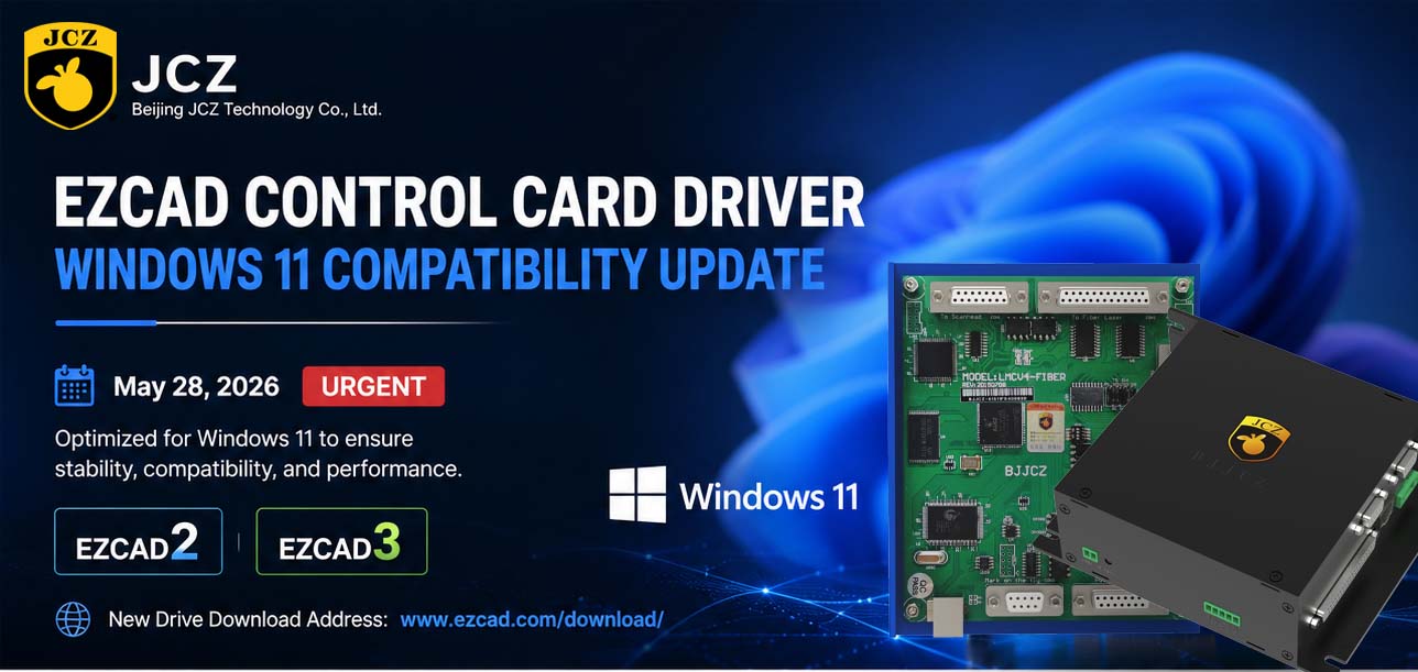
OFFICIAL DRIVER UPDATE NOTICE
Top Factors That Affect Marking Quality in Handheld Fiber Laser Systems

Meet JCZ at Laser World of Photonics India 2026 in Bengaluru
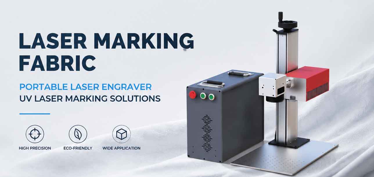
Laser Marking Fabric with Portable Laser Engraver: Advanced UV Laser Marking Solutions for Modern Manufacturing
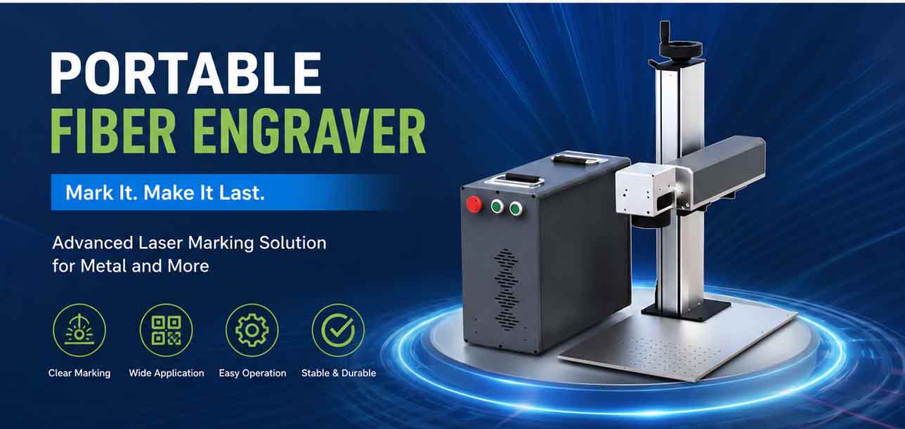
Laser Machine for Marking: The Ultimate Guide to Portable Fiber Engravers & MOPA Color Laser Marking

Laser Cleaning Machine for Wood: The Ultimate Guide to Safe, Precise & Eco-Friendly Wood Surface Cleaning