Trends in Enclosed Laser Marking Cell Integration
Bringing a laser marking process into a fully enclosed cell is no longer a niche choice — it’s fast becoming the baseline for manufacturers who need repeatable part traceability, uncompromised operator safety, and streamlined automated lines. As production floors move toward lights‑out operation and tighter supply‑chain documentation, the way we integrate the marking engine, the motion system, the software, and the safety logic inside one interlocked enclosure has shifted decisively. For system integrators and in‑house automation teams, understanding these integration trends is what separates a cell that runs 24/7 from one that becomes a bottleneck after six months. JCZ, the creator of the EZCAD platform, has been at the center of that conversation, supplying the laser sources, galvanometer scanners, and software backbone that many enclosure builders rely on.
Over the last three years, industry reports suggest the global laser marking market has grown at a compound rate near 7 %, with enclosed workstation solutions capturing an increasing share because of updated laser‑safety regulations and the push for clean‑room‑compatible manufacturing. The trends cut across hardware, control architecture, and connectivity. What follows is an engineer’s look at where enclosed laser marking cell integration is headed, what’s driving the change, and how control software in particular — from basic 2D jobs to multi‑axis flying marking — is redefining what a cell can deliver.
Why enclosures have moved from optional to standard
A decade ago, a Class‑4 laser often sat inside a simple acrylic box with a door switch. Today’s cells are different animals. The first driver is straightforward regulation: standards such as IEC 60825‑1 and ISO 11553‑1 specify that any integrated laser processing machine must ensure that accessible radiation stays below the maximum permissible exposure limits. For industrial Nd:YAG or fiber lasers operating at tens of watts for deep engraving, a robust interlocked enclosure with light‑tight seals and monitored safety circuits achieving Performance Level d (PLd) or better is not a recommendation — it’s a requirement. Closed cells also let you control fume extraction precisely. When marking plastics, stainless steel, or coated metals, the local exhaust ventilation typically needs to meet a minimum capture velocity of 0.5 m/s at the source, and the returning air may require HEPA H13 filtration (99.95 % efficiency for 0.3 μm particles) to protect both workers and sensitive assembly areas nearby.
The second trend is more about process control. An enclosed cell stabilizes the environment around the laser beam path. Optical surfaces stay cleaner, the parts rest in a known fixture, and the temperature drift that can move a galvanometer’s zero point is minimized. This directly feeds into marking repeatability: work‑holding positions become permanent, and even small markings such as 2D codes on medical devices can be positioned within ±10 μm consistently. For JCZ’s Elite Series nanosecond lasers, which deliver a beam quality of M² <1.2 and flexible repetition rates from 50 kHz to 5 MHz, that environmental stability means the spot size on the workpiece doesn’t wander across a shift, preserving the fine‑line precision engineers count on for UDI codes and micro‑engraving.
The laser engine inside the cell: more wavelengths, less footprint
Ten years ago you’d design a cell around a bulky lamp‑pumped laser and a stand‑alone chiller. Today the laser head itself is often small enough to mount directly on a robotic end effector or inside a tight machine frame. Compact air‑cooled designs, like JCZ’s all‑in‑one Elite Series that covers IR, UV, green, and red wavelengths, simplify cell design dramatically. Instead of routing water loops and worrying about condensation in a humidity‑controlled enclosure, you mount the laser, plug in power and a control signal, and route the beam via a galvo scanner. UV lasers (355 nm) are particularly relevant for enclosed cells processing plastics and glass, because the short wavelength creates a photochemical “cold” mark with minimal heat‑affected zone — often below 5 μm in depth, which is critical for electronic parts and medical components. Green lasers (532 nm) handle highly reflective metals like copper and gold without the need for high peak power, reducing the enclosure’s laser conditioning requirements.
The AOFEMTO series femtosecond laser is another step change for precision‑heavy cells. With pulse durations in the hundreds of femtoseconds, the material removal is athermal, practically eliminating burr and recast. When marking surgical instruments or fuel injection components inside a Class‑1000‑compliant enclosure, the athermal process means no spatter to clean and no micro‑cracks to inspect. The typical machining accuracy can be held under ±1 μm in such setups — numbers that are impossible to achieve with open‑air setups subject to vibration and airborne dust. The fume extraction system itself becomes simpler because the ablation byproducts are different; fewer heavy particles require the filtration train, and you can often get away with a smaller filtration unit inside the cell base, saving floor space.
Software as the integration bus: beyond “print and wait”
If the enclosure is the body and the laser is the muscle, the control software is the nervous system. Here’s where factory engineers spend most of their integration time, and where the decision to use a particular platform cascades through the whole cell design. Many closed cells run on a standard 2D marking job list loaded via USB, but high‑mix production demands dynamic data handling. For instance, a cell marking serial numbers on automotive sensors needs to pull data from an MES database, change the mark content per part, log the result, and then handshake with the robot that loads the next tray.
That’s where the choice of Laser Software becomes pivotal. The EZCAD ecosystem, built into millions of laser control boards worldwide, is the de facto standard for a reason. In an enclosed cell, the software must handle more than just turning the laser and galvo on and off. It must coordinate rotary axes for round‑part marking, manage dual‑axis stitching when the marking field exceeds the scanner’s natural area, and feed position data to the safety PLC so the enclosure door can unlock only after the marking head has homed and the laser is shuttered. With Ezcad2 Software, integrators get rock‑solid dual‑axis splicing and flying marking modes that are valuable when the cell includes a conveyor that doesn’t stop. The ability to mark a stream of parts on‑the‑fly at line speeds up to roughly 60 m/min — a typical capability for hot‑marking code systems — cuts the required cell footprint because you’re not accumulating parts, and it removes the stop‑start mechanical loads that wear out indexing fixtures.
For cells that push precision limits, Ezcad3 Software takes a different architectural approach. Its fully 64‑bit data path dramatically shortens the time from sending a marking job to the actual galvanometer movement, which matters when you’re populating a dense matrix of marks on a 300 mm × 300 mm panel. Delays that were once hidden by mechanical indexing now become visible as visible idle dwells. In practice, cells running Ezcad3 report noticeably smoother trajectory blending, especially when executing multi‑line vectors and complex hatching on curved surfaces. The software can also interface more cleanly with high‑resolution encoders on rotary stages, allowing the laser to compensate for axis wobble in real time. This is key for integrators who want a single software environment for both basic 2D marking and demanding 3D‑like processes such as deep engraving with incremental z‑axis movement — all inside a sealed cell with a closed‑loop environment monitor.
Flying marking, data logging, and the pulse of the automated line
One trend that’s reshaping enclosure design is the shift from batch processing to in‑line continuous marking. Traditional enclosed cells are fed by a pick‑and‑place arm: the door opens, the part goes in, the door closes, the mark fires, the door opens. That sequence adds 3 to 5 seconds of non‑marking time per cycle. Multiply by millions of parts, and it’s a meaningful cost. Flying marking inside a cell — where the laser tracks the part as it moves on a conveyor — eliminates the door cycle for many applications. To do this safely, the cell must still contain the laser radiation, which means a tunnel‑style enclosure with entrance and exit baffles or light‑resistant curtain walls. The laser beam itself is contained, but the conveyor passes through. The control board, typically a JCZ flying‑marking control system, receives encoder pulses from the conveyor belt and adjusts the mark coordinate system in microseconds. The result is a clean mark applied to a moving product without slowing the line. This flying‑marking approach is heavily adopted in food and beverage and extruded plastic industries, where product traceability codes must be applied at rates exceeding 10,000 parts per hour. The challenge for the integrator is aligning the laser’s field‑of‑view with the product sensor so that the marking position remains within ±0.2 mm of the intended spot, even as belt tension changes.
On the data side, enclosed cells are becoming nodes in plant‑wide quality networks. A modern cell using Ezcad’s SDK — available for both 32‑bit Ezcad2 and 64‑bit Ezcad3 platforms — can expose every marking parameter, galvo temperature, and laser‑pulse count to a supervisory system via OPC‑UA or MQTT. For an automotive Tier‑1 supplier, that means a mark‑verification camera inside the cell can trigger a requeue signal to the robot if the Data Matrix score falls below ISO 15415 grade B, all without a separate PC. The integration happens at the API level, so the cell’s core logic is a single piece of safety‑rated PLC code that talks to the laser control board through the SDK. JCZ’s open secondary‑development platform has allowed integrators to create custom operator panels that run on the same industrial PC as the cell’s vision system, reducing hardware count. From a maintenance perspective, having the entire mark job history — including galvo‑setpoint waveforms — stored in a SQL database makes traceability audits straightforward. Instead of “maybe the mark degraded over time,” you can review the actual scan‑head servo lag from two weeks ago and decide if preventive maintenance is due.
Hardware and layout: smaller, smarter, easier to certify
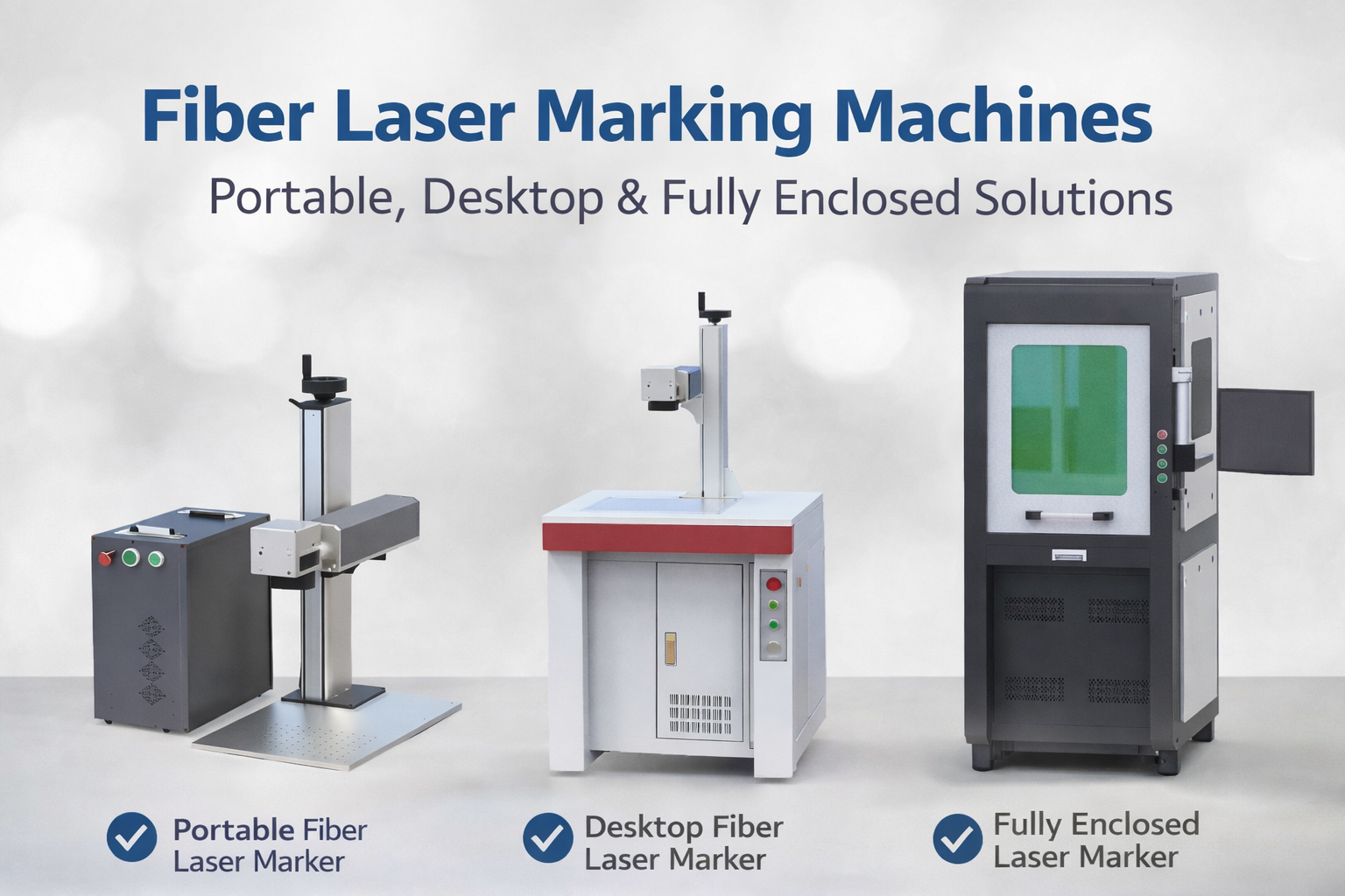
The shrinking of laser components is changing how enclosures are laid out. A PF‑2D or PF‑2.5D high‑performance marking system integrates the galvo scan head and focusing optics into a single compact block that can be ceiling‑mounted inside a small cell. The laser source, if it’s an air‑cooled Elite nanosecond unit, can sit in a side‑pocket cabinet with the driver board. This modularity lets system builders offer a base enclosure platform that they can configure with different laser wavelengths and scan‑field sizes without re‑engineering the safety circuit. The certification cost per variant drops because the safety architecture stays the same; only the light‑shielding calculations need updates.
Materials inside the enclosure are maturing, too. The default interior was once black anodized aluminum, which might reflect some scattered laser energy. More cells now use textured matte stainless steel or laser‑absorbing polymer laminates on non‑functional walls. The measured scattered radiation outside the cell must stay below Class‑1 accessible limits, and a well‑designed enclosure with internal beam dumps and baffles can achieve that with a laser source up to roughly 100 W average power, provided the viewing windows have the correct optical density rating for the specific wavelength. An often‑cited design target is a window with OD 6 at 1064 nm for a fiber laser cell, which attenuates the transmitted beam to 1‑millionth of the incident power. The integration team must verify that with a power meter during commissioning, and document the test results as part of the technical file for CE or NRTL marking.
| Integration Aspect | Traditional Open Setup | Enclosed Cell Trend |
|---|---|---|
| Laser safety | Rely on operator PPE and curtains | Interlocked Class‑1 enclosure with certified safety circuit |
| Fume extraction | Ambient room ventilation, often insufficient | HEPA H13‑14 extraction tied to cell interlocks |
| Mark positioning repeatability | ±50 μm typical, subject to environment | ±10 μm achievable with stable fixture and temperature control |
| Software control | Standalone PC, manual file loading | MES‑connected, SDK‑driven, supports flying marking & data logging |
| Multi‑wavelength flexibility | Separate heads, long changeover | Single galvo head with laser swapping via shutter or turret |
| Typical mark‑rate for in‑line flying marking | Not feasible without safety difficulty | Integrated encoder‑synchronized marking at 60 m/min line speeds |
The people side: operator trust and maintenance simplicity
An often overlooked trend is the effort to make enclosed cells less intimidating to operators. A cell that looks like a black box gets ignored during daily checks, and minor issues like a dirty protective window compound into marking failures. Modern enclosures include large laser‑safe viewing windows so the operator can see the marking spot — with appropriate eye protection for the OD value — and status‑light bars that signal job complete, ready, or fault. Maintenance becomes a key integration metric: can you replace the galvanometer scanner without breaking the safety seal? JCZ’s high‑stability, high‑speed galvo scanners are designed so that in a well‑planned cell, the scan head can be accessed from the top of the enclosure without completely removing the light‑tight shell. The cell builder pre‑fits alignment‑doweled mounting plates so that swapping a scanner takes 15 minutes instead of a full day of realignment.
Daily verification is also being streamlined. Instead of a full‑system teardown, many cells incorporate a calibration target and a pre‑programmed test mark. The operator loads a test coupon once per shift, presses a button, and the cell runs a cross‑hair and a small Data Matrix while the internal camera checks position and code quality against set limits. This five‑minute ritual, combined with an automated laser‑power‑check sequence using an onboard photodiode, captures system drift before it causes a reject batch. The software logs the data, and the SDK makes it easy for integrators to build that workflow without hiring a dedicated vision programmer.
Frequently Asked Questions
What safety certifications do enclosed laser marking cells typically need?
Most require CE marking per the Machinery Directive 2006/42/EC, referencing EN ISO 11553‑1 and IEC 60825‑1 for laser‑specific hazards. In North America, ANSI Z136.1 applies and the cell must be listed by an NRTL to UL 61010‑1. Documentation must include laser‑power measurements and the optical‑density calculation for every viewing window.
Can I integrate a vision system for mark verification directly through the laser control software?
Yes. Using the Ezcad3 Software or its predecessor through the Ezcad2 Software SDK, you can trigger a camera, grab the image, and perform a decode‑and‑grade routine from within a custom application. This avoids the latency of a separate PC and lets the cell’s PLC react immediately if a mark fails to meet the required grade.
How does flying marking work inside a fully enclosed cell?
A conveyor passes through a light‑tight tunnel built into the cell. An encoder tracks conveyor position and the JCZ flying‑marking control board dynamically shifts the marking coordinates to match the moving part. The laser remains fully enclosed, so operators never access the beam path; only the product enters and exits through guarded openings. This method enables marking speeds matching lines up to 60 m/min or more, without stopping the belt.
What is the practical cleaning and maintenance interval for an enclosed cell’s optics?
In a filtered enclosure, the protective glass window in front of the galvo scanner typically needs cleaning every 200–400 operating hours, depending on the material being marked. A HEPA‑filtered positive‑pressure environment can push that interval beyond 1,000 hours. We recommend an integrated power‑loss sensor that alerts when the window needs attention, preventing gradual quality drift.
Is it possible to upgrade an existing open laser marker into an enclosed cell later?
Retrofitting is possible if the laser and scanner allow remote‑control interfacing, which JCZ boards do through the SDK, and if you can fabricate a proper enclosure with interlock‑adapted safety circuits. However, a better long‑term approach is to design the cell from the start for a specific line requirement, because retrofits often compromise extraction efficiency and make compliance documentation more complex.
The evolution of enclosed laser marking cells doesn’t stand still. The next few years will bring tighter integration between safety‑rated controllers and laser‑control boards, with real‑time diagnostics moving from the shop floor to the cloud, letting factory managers view marking OEE from any browser. For the integrator, staying ahead means choosing a control platform that is open enough to talk to any automation stack, yet mature enough that you won’t spend weeks chasing buffer overruns. With a proven software ecosystem that spans Laser Software from basic 2D jobs to multi‑axis 3D inner engraving, and with compact, wavelength‑flexible lasers that keep the cell footprint manageable, the tools already exist to build cells that meet the most demanding traceability targets. The remaining challenge is simply applying sound engineering discipline: design for serviceability, document the safety case meticulously, and treat the software‑hardware link as the critical element it has become.
OFFICIAL DRIVER UPDATE NOTICE
Trends in Enclosed Laser Marking Cell Integration

2026 Mid-Autumn Festival and National Day Holiday Notice

Top Factors That Affect Marking Quality in Handheld Fiber Laser Systems

Meet JCZ at Laser World of Photonics India 2026 in Bengaluru
Laser Marking Fabric with Portable Laser Engraver: Advanced UV Laser Marking Solutions for Modern Manufacturing