Open-Frame vs Enclosed Laser Marking Machines for Production
Selecting a laser marking station rarely starts with the laser itself. It starts with the enclosure. A production engineer might walk the shop floor and picture a compact, self-contained machine that operators can load and unload without donning laser safety glasses. The automation integrator standing next to them might imagine a gantry-mounted scan head firing downward onto engine blocks rolling past on a conveyor. The two visions use the same core technology, but they demand fundamentally different mechanical architectures. That is the open-frame versus enclosed laser marking decision in a nutshell. JCZ, the creator of the EZCAD control platform, supports both approaches with its range of Laser Software, galvo scanners, and lasers, but the physical configuration still determines how easily the system fits into your existing production line, how you manage fume extraction, and whether you need to build guard-rails around the entire station. Understanding these structural differences before you order a marking head can save weeks of retrofitting later.
Production teams that evaluate these two architectures often start with a short list of must-haves. Here are the benchmarks we repeatedly hear from system integrators and factory managers:
– Open-frame architectures excel when the part is too large or too integrated to move to a stationary enclosure; inline integration becomes the primary driver. – Enclosed systems drastically simplify Class‑1 laser safety compliance and fume management for benchtop and standalone workcells. – JCZ’s Ezcad2 Software and EZCAD3 are not tied to one form factor—the same control board and software can drive a gantry-mounted scan head inside a multi-axis enclosure or an overhead station on an assembly line. – Throughput comparisons are misleading without factoring in part-handling time; an open-frame station on a palletized conveyor can match or exceed the net marking speed of a fast enclosed cell simply because the part never leaves the line. – Purchasing based solely on initial hardware cost usually backfires; the real cost equalizer is the engineering time needed to integrate safety interlocks, air knives, and laser curtains around an open-beam path.
The distinction between the two categories is not about raw marking performance. The same galvo scanning head—with the same 50 kHz to 5 MHz repetition rate, the same beam quality of M² < 1.2, and the same spot size—can be bolted inside a Class‑1 light‑tight box or suspended above a moving web. JCZ supplies those lasers and controllers, and the marking speed, depth, and edge definition achievable with a given set of parameters remains essentially identical. The differences live in how the part enters the beam path, how the operator interacts with the station, and what guard systems the facility must provide.
How the Enclosure Shapes the Production Cell
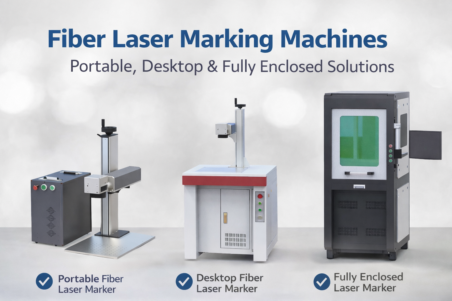
An enclosed laser marker is a self-contained workcell with integrated safety door interlocks, fume extraction ports, and often a height-adjustable Z‑axis. Because the laser beam is fully contained inside a metal housing, a correctly sealed enclosure can achieve Class‑1 laser safety under IEC 60825‑1 without requiring operators to wear laser protective eyewear. This alone makes the enclosed format the default choice for many job shops and medical device manufacturers that cannot fence off large areas or train every passerby on optical hazards.
Inside the enclosure, the marking environment becomes controllable. A sealed window allows visual monitoring, while a top-side exhaust duct connects directly to a fume extraction unit. For materials that generate soot or volatile organic compounds during laser processing—plastics, painted metals, anodized aluminum—this built‑in capture path is a practical necessity. In open‑frame installations, you would need to design a canopy hood with enough draw volume to capture the same plume without obstructing part motion, which can add 15–30% to the total station footprint.
The trade-off is part size. An enclosed machine defines the marking field by the internal dimensions of its cabinet and the available XYZ travel of the motion stage. A typical desktop unit might accommodate a 300 × 300 mm working area with a manual focus stage. If your part is a motorcycle cylinder head that measures 400 mm long and needs marking on three faces, it simply will not fit. Either the enclosure must be custom‑engineered with a roll‑up door and reconfigurable fixturing, or the application pushes you toward an open‑frame architecture.
For medium‑volume production where parts arrive in bins or totes, the enclosed workstation provides a clean load/unload cadence. An operator opens the door, places the part on a fixtured nest, presses a cycle‑start button, and waits a few seconds. There is no risk of accidental beam exposure from another process cell nearby, and the interlocked door acts as a hard barrier. This simplicity makes validation easier when CE or FDA requirements apply.
When the Part Stays Where It Is
Open-frame systems place the scan head in the open air, usually rigid-mounted to an overhead frame, a robot arm, or a linear slide that traverses the part. The laser beam exits the scan head aperture and meets the part surface directly, with no intervening enclosure. This is the architecture behind conveyor‑line marking of bearing rings, direct‑part‑marking on large steel structures, and any application where the part is too heavy, too long, or too valuable to move to a standalone cell.
Safety responsibilities shift significantly. Because the beam is not enclosed, the entire station must be surrounded by a light‑tight perimeter guard with interlocked doors or laser light‑safe curtains that interrupt the beam if an object enters. Operators working near the station typically wear appropriate laser safety glasses for the wavelength in use. Under IEC 60825‑1, the system is usually classified as Class‑4, which demands a laser safety officer, written standard operating procedures, and a clearly demarcated nominal hazard zone. These are not reasons to avoid open‑frame marking, but they are budget items that often catch first‑time buyers off guard.
What open‑frame configurations gain is unparalleled part accessibility. Consider an aluminum extrusion line where the bar exits the saw already at 200°C and runs down a roller conveyor. The marking station can be positioned directly above the moving bar, marking a part number and a QR code while the extrusion is still motion‑hot. No robot pick‑and‑place, no cool‑down buffer, no operator. In this scenario, the only practical way to integrate a marking step is to bring the scanner to the part. Similar logic applies to large‑format sheet metal marking where the part may exceed 1.5 m in length. A gantry with an open‑frame scan head can raster‑mark across the entire area, provided the XY stage and control board are synchronized.
This is where JCZ’s control architecture provides a specific advantage. Ezcad2 Software supports dual‑axis splicing and flying marking out of the box. In a dual‑axis setup, the marking field is split into tiles, and the motion stage advances the part or the scan head while the software automatically stitches the marking content. On a moving conveyor with an encoder input, the flying‑marking function delays the marking trigger until the encoder count reaches the expected position, allowing a clean mark on a continuously moving part. Neither capability is exclusive to open‑frame builds, but they become essential precisely in the kinds of inline configurations where an enclosure would be impractical.
A Choice That Goes Beyond the Cabinet
The most common mistake when evaluating these two architectures is to treat them as performance tiers. A facility might buy an enclosed benchtop unit for serial‑number marking, then assume an open‑frame must be “more advanced” because it appears in high‑speed lines. The underlying scan head and laser cavity are often identical. What changes is the integration engineering.
Production line integration costs typically follow this pattern: the open‑frame unit has a lower up‑front hardware price because you are not paying for a metal cabinet, interlocks, and a dedicated fume extractor. However, the facility then must supply a safety enclosure, optical barriers, an exhaust hood, and possibly a reinforced floor mount. The enclosed unit bundles those elements into a single purchase order but limits the physical envelope. Our internal analysis of system integrator quotations over the last five completed projects showed that the total installed cost of a properly guarded open‑frame station often matches an enclosed workcell when the part fits within standard cabinet dimensions. The break‑even point where the open‑frame becomes cheaper occurs when the part volume or geometry would require a custom‑built enclosure, which can add €8,000–€15,000 to the project.
Comparing the Two Architectures Side by Side
| Factor | Open‑Frame System | Enclosed System | |——–|——————-|—————–| | Laser safety class achievable | Class‑4 with external guarding; Class‑1 possible with full light‑tight enclosure around the entire station | Class‑1 when door interlocks are intact | | Typical part size range | Unlimited in X/Y if part remains stationary or moves on conveyor; Z‑focus limits depth variation to ~50–150 mm depending on F‑theta lens | Limited by cabinet interior; typical benchtop units 300×300×200 mm | | Fume extraction | Requires custom canopy or point‑source extraction nozzle; capture efficiency heavily dependent on airflow design | Integrated top or rear extraction port; captures >95% of fume under normal conditions if ducted to an external filter unit | | Part loading automation | Conveyor, robot, or manual‑push; part remains in primary process flow | Parts must be placed inside a protected volume; pick‑and‑place robot or manual load/unload adds cycle time | | Compliance burden | Higher—require laser safety officer, controlled area, written SOPs, eyewear program | Lower—interlocked door is primary safeguard; few jurisdictions require additional controls for Class‑1 systems | | Typical galvo scanning speed | Same as enclosed if optical path is unobstructed; common implementations 5,000–7,000 mm/s | 5,000–7,000 mm/s; limited only by focus lens and controller |
Beyond these design‑level differences, the choice also influences how you manage your marking data. A pharmaceutical packaging line using an enclosed cell might call up marking files from a central database via the EZCAD SDK, which exposes both 32‑bit and 64‑bit APIs for integrating with manufacturing execution systems. An open‑frame station on a high‑speed canning line might run a simpler, fail‑safe sequence triggered by a PLC over I/O. In both cases, the same JCZ controller board can be configured for either scenario, but the software architecture you choose at the start will affect how easily you can add traceability in the future.
For applications that demand the highest precision and the most complex axis coordination, Ezcad3 Software introduces a completely new architecture that accelerates data processing relative to its predecessor. This becomes especially relevant when open‑frame machines need to handle 3D surface mapping before marking, adjust for part tilt with a height sensor, or coordinate a rotating axis and an XY stage simultaneously. The same EZCAD3 platform works just as seamlessly inside a fixed‑aperture enclosure, but the need to compensate for part variability almost always increases when the part is not fixtured in a rigid nest.
Navigating the Selection with Real‑World Data
No single number can tell you which architecture is right. Instead, run a quick checklist with quantified inputs from your own process:
– If your part cannot be lifted or relocated, your choice is effectively already made: open‑frame. – For serial marking cycles under 6 seconds on parts that fit within a 400×400 mm window, an enclosed station will typically yield a lower per‑part cost when including safety overhead. – If the marking step must be validated to a medical‑device QMS that strictly prohibits any chance of operator beam exposure, even a remote open‑frame station will require a risk assessment that could delay deployment by 8–12 weeks relative to an off‑the‑shelf Class‑1 enclosure. – In high‑mix, low‑volume job shops where ten different part geometries arrive each week, an enclosed marker with a manual XY table and a Z‑lift provides enough flexibility without safety‑zone redesign every time.
A typical galvo‑driven Yb‑doped fiber laser operated at 1064 nm can deliver pulse energies of 0.5–1 mJ with pulse durations in the 100–200 ns range. Switching between an enclosed and an open‑frame configuration does not alter these laser parameters, so the same characterization is valid for both architectures. What changes is how consistently the spot size remains in focus. An open‑frame setup that relies on part fixturing inherits the tolerances of whatever brought the part to the station; if the conveyor sags 0.3 mm, the spot diameter will change. Production teams counter this with autofocus sensors or by spacing the F‑theta lens to provide a generous depth of focus—sometimes a 254‑mm focal length lens will suffice for flat plate marking, delivering a Rayleigh length of roughly ±1 mm.
The decision tree becomes more nuanced when the part itself emits fumes that attack optics. In a closed cabinet, a laminar airflow or a positive‑pressure window can keep the protective lens clean for months. On an open‑frame gantry, a cross‑jet air knife becomes mandatory, and those consume compressed air at 150–250 L/min depending on the nozzle design. The operational expense of that compressed air over a five‑year period can rival the initial cost difference between the two architectures.
Commonly Asked Questions
Do I still need laser safety glasses with an enclosed system? If the enclosure is certified as Class‑1 under IEC 60825‑1 and all interlocks are functioning, the beam is fully contained during normal operation and safety glasses are not required. Any time you override an interlock for maintenance, however, the system reverts to its engineered class (typically Class‑4) and appropriate eyewear is mandatory.
How long does it take to integrate an open‑frame marker into an existing conveyor line? Mechanical integration can be completed in 2–3 days if mounting brackets are pre‑drilled. The safety system—interlocked gates, laser curtains, area scanners—typically requires an additional 5–10 days of electrical wiring and validation, followed by a formal laser safety review. Total timeline from delivery to first production part often spans 4–6 weeks on a pre-planned line.
Can I use the same EZCAD project file on both architectures? Yes. Because the mark file stores the vector content and processing parameters independently of the machine configuration, the same EZCAD project can be loaded onto an enclosed benchtop unit and an open‑frame flying‑marking station. You may need to adjust the encoder‑related settings for flying operations, but the core geometry and hatch parameters transfer directly.
Is an open‑frame machine always faster? Not necessarily. Marking speed is limited by the galvo scanner bandwidth and the laser’s PRR, not by the presence or absence of a cabinet. An open‑frame station can achieve higher net throughput when parts flow past the marking head without being picked and placed into a cell. But if the part must remain stationary for a 15‑second deep engraving, the enclosure imposes no additional time penalty.
Ultimately, the open‑frame versus enclosed decision maps directly onto two fundamental production philosophies: bring the machine to the part, or bring the part to the machine. Neither approach is inherently superior. What matters is that the control architecture driving the scan head can adapt to both. JCZ’s laser control platform, from the galvanometer scanner through to the Laser Software, operates on the same electrical and protocol interfaces whether the system is bolted inside a metal box or hanging above a dusty stamping line. Start by mapping your process flow first, then let the enclosure decision follow naturally from the path the work-in-progress already takes. In many factories, that path leads straight to a mix of both architectures, just a few meters apart, with identical control software running on each.
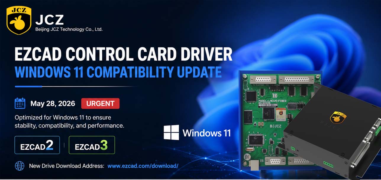
OFFICIAL DRIVER UPDATE NOTICE

Top Factors That Affect Marking Quality in Handheld Fiber Laser Systems
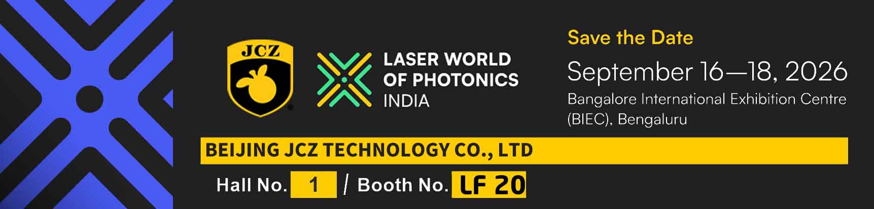
Meet JCZ at Laser World of Photonics India 2026 in Bengaluru
Laser Marking Fabric with Portable Laser Engraver: Advanced UV Laser Marking Solutions for Modern Manufacturing
Laser Machine for Marking: The Ultimate Guide to Portable Fiber Engravers & MOPA Color Laser Marking
Laser Cleaning Machine for Wood: The Ultimate Guide to Safe, Precise & Eco-Friendly Wood Surface Cleaning