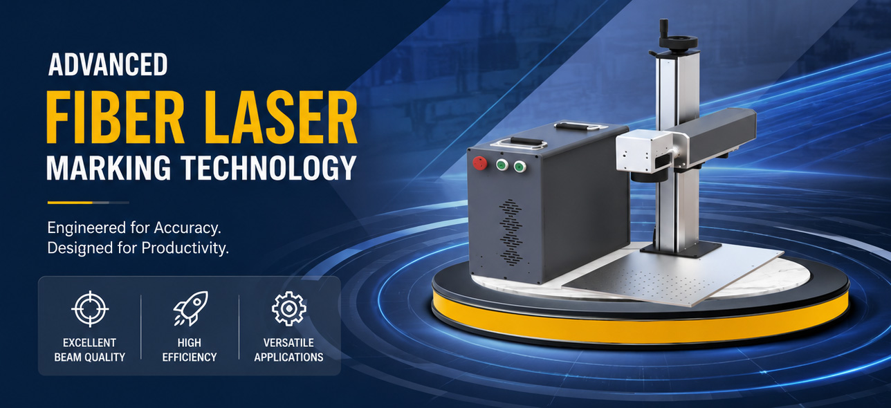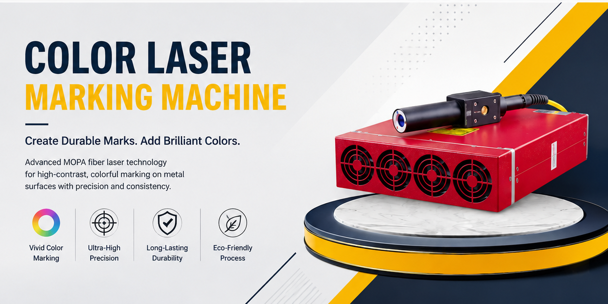
Portable Fiber Laser Marker Buying Guide for Large and Fixed Workpieces
A lathe bed casting weighing two tons sits on the factory floor. A structural steel column already welded into place awaits part-number marking. Traditional laser marking stations expect you to bring the workpiece to the machine. When the workpiece cannot move—or moving it costs more than the marking job itself—you bring the machine to the workpiece. That’s the core logic behind portable fiber laser markers, and it’s why more heavy-industry buyers are evaluating them against conventional gantry or fixed-station setups.
This guide examines what actually matters when you need to mark large, immovable parts: the controls architecture, the beam delivery, the software muscle behind the marker, and the physical ergonomics that determine whether an operator can handle an eight-hour shift. We’ll tie each factor back to measurable specs and standards, not marketing claims, so you can compare units without leaning on sales brochures. When you finish reading, you’ll know how to match a portable fiber laser marker to the kind of jobs where a crane isn’t in the budget.
Why a cart-mounted enclosure won’t cut it for large workpieces
Standard benchtop laser markers enclose the entire beam path in a fixed housing with a limited working distance. You get a marking area defined by the F-theta lens—typically 100 × 100 mm up to 300 × 300 mm for a field-flattening optic. That’s fine for nameplates and small components. For a ten-meter steel girder that needs marks at multiple positions, you either move the part (impossible on a job site) or you build custom motion stages that cost more than the laser source.
Portable fiber lasers address this by separating the scan head from the control unit and laser engine. The operator holds a handpiece or positions a tripod-mounted galvanometer head directly on the workpiece. The fiber delivery cable—typically 2 to 5 meters long on ruggedized systems—carries the beam while keeping the sensitive electronics away from dust, rain, and temperature swings. A few critical numbers come into play immediately: the head mass must stay under about 2.5 kg to prevent operator fatigue (ergonomic standards like ISO 11228-1 suggest sustained one-handed tool handling is acceptable below this weight when well-balanced). The minimum bend radius of the armored fiber is usually specified at 200 mm or less; exceed it and you risk micro-cracks that degrade beam quality over the fiber’s 100,000‑hour typical lifespan.
Laser source performance: watts, pulses, and why M² matters more than peak power
Laser type choice defines what materials you can mark and how deep. Fiber lasers based on ytterbium-doped active fibers emit at 1064 nm—well absorbed by ferrous and non-ferrous metals but nearly transparent to many organics. JCZ’s Elite Series nanosecond lasers, for example, offer a compact all-in-one design with selectable wavelengths (IR, green 532 nm, UV 355 nm, and red options) and a beam quality of M² < 1.2 (per product technical data). That M² number tells you how tightly the beam focuses; values under 1.3 are considered near-diffraction-limited and allow spot sizes down to roughly 20 µm with appropriate optics. For deep engraving on tool steel or titanium, a 50 W average-power fiber laser (pulsed, with peak powers in the kilowatt range) can achieve engraving depths of 0.1–0.3 mm per pass, depending on pulse energy and overlap.
A few other specs ground your comparison in reality. – Pulse repetition rate: The Elite Series spans 50 kHz to 5 MHz, giving a wide tuning window. Low rep rates (50–200 kHz) generate high pulse energy for deep engraving; high repetition rates (>1 MHz) smooth out the surface when marking anodized aluminum or thin coatings. – Pulse width: Typical nanosecond pulses range from 10 ns to 200 ns. Shorter pulses (10 ns) produce sharper edges with less heat-affected zone; longer pulses (100 ns) remove more material per shot but increase the HAZ, which can matter if you’re marking through a zinc coating without burning the base steel. – Cooling: Fiber lasers in the sub-100 W class normally use forced-air cooling, consuming under 600 W total system power. That’s a practical detail for portable use—no water chiller means you can plug into a standard 220 V AC outlet on a construction site, provided voltage stability stays within ±10 % per IEC 60204-1.
The galvanometer scanner and lens: where portability hits physics
The fastest laser source means nothing if the scanner can’t direct the beam accurately over the whole mark field. In portable setups, the scan head—containing two moving-mirror galvanometers and a focusing lens—must survive being clamped to a vibrating workpiece while maintaining repeatable spot placement.
Galvanometer performance specifications you should ask for: – Small-angle step response time: around 0.3–0.5 ms for a 0.1 mm step. Faster response lets you run higher marking speeds (typically 5,000–10,000 mm/s vector speed on flat metal) without rounding corners. – Repeatability: ±8 µm to ±12 µm is achievable in industrial-grade scanners (referenced to ISO 9283, which benchmarks path accuracy for manipulators). This translates to text that stays crisp even after dozens of repositioning cycles on a large part. – Field flatness: F-theta lenses correct barrel and pincushion distortion so that a mark at the edge of a 200 × 200 mm field is as sharp as one at the center. Lens quality is expressed by the telecentricity error—below 0.5° keeps dot geometry consistent across the field, which matters for 2D codes read by scanners.
When you move the scan head instead of the part, you introduce positioning variables. A magnetic V-block or a tension strap can hold the head against a steel surface, but mechanical alignment still determines whether a row of marks follows a true horizontal line. Operators often use a built-in red-diode pointer visible through the F-theta lens to pre-align. Some systems offer crosshair overlays in the control software to compensate for head tilt by digitally rotating the mark file.
Software—the brain that makes portability practical
The entire system’s usability hinges on Laser Software that does more than send G-code to a galvanometer. For large workpieces that demand stitching, field-mapping, and variable power across a single job, the software must handle coordinate splitting and dynamic corrections without crashing mid-file. JCZ’s EZCAD family has been the industry standard for many Chinese and European laser integrators because it evolved alongside the hardware it controls.
Ezcad2 Software delivers dual-axis splicing and flying marking as native functions. Dual-axis splicing lets you define a virtual canvas larger than the optical field—say, a 600 × 600 mm area—and the software automatically partitions the object into tiles. You reposition the scan head after each tile, trigger a new alignment, and continue marking with a positional offset of ±0.05 mm when properly calibrated. Flying marking matters for production lines where the laser codes parts in motion, tracking encoder signals on a conveyor. For portable use, this mode can also lock onto a moving workpiece, such as a pipe slowly rotating on rollers during weld-seam marking.
Where projects demand sub-micron precision or large file sizes with complex vector layers, Ezcad3 Software steps in with a completely new 64-bit architecture that slashes data processing latency. On a 3 GB engraving file with hundreds of thousands of vectors, the older 32-bit engine might introduce a few seconds of lag during decompression; EZCAD3 races through it with noticeably faster galvo streaming, which becomes critical when you’re stitching high-density QR codes across a one-meter-long stainless steel plate. The software also includes advanced beam modulation for deep 3D engraving—useful for mold cavities where depth must vary within a single layer. For integrators writing custom factory-floor interfaces, the EZCAD SDK provides both EZCAD2 32-bit and EZCAD3 64-bit libraries, supporting functions from simple bitmap loading to multi-layer power mapping.
The SDK is more than an afterthought: it embeds the entire mark engine into your own ERP‑connected application, so an operator scans a barcode on a massive casting, the server sends back serial data, and the laser appends the traceability code without anyone touching the keyboard. That level of automation collapses what would otherwise be a multi-step manual alignment into a single scan-trigger-mark cycle.
Matching mark field to workpiece size: practical starting points
There is no single “right” lens for large workpieces; you pick based on the smallest feature you need to resolve and the largest unbroken area you want to mark in one position. The table below gives typical working distances and spot sizes for common F-theta lens focal lengths at 1064 nm with M² ≈ 1.2—data drawn from standard optical design references and validated by real-world galvo-lens pairings.
| Focal length (mm) | Mark field (mm) | Approximate spot size (µm) | Typical working distance (mm) | Best use case for large workpieces | |——————-|—————–|—————————-|——————————-|———————————–| | 100 | 65 × 65 | 20–25 | 110 | Tiny, high-contrast barcodes | | 163 | 110 × 110 | 30–35 | 180 | Tags within a recessed pocket | | 254 | 180 × 180 | 45–55 | 280 | Logo and data on beam flanges | | 330 | 220 × 220 | 60–70 | 360 | Large text on structural steel | | 420 | 300 × 300 | 80–100 | 450 | Full-field serial numbers on plates |
If your mark needs to span 500 mm in one dimension, you’ll either need a larger lens (which becomes heavy and optically slower) or rely on splicing. Splicing with a 254 mm lens typically yields a practical stitch accuracy around ±0.1 mm after a two-point alignment routine, good enough for human-readable text but borderline for 2D codes that require tight cell spacing. For codes, a single-shot field is safer: choose a lens whose field covers the entire code plus a quiet zone.
Another nuance: the depth of focus of a 254 mm lens at this spot size is about ±0.5 mm. On a large casting with surface roughness Ra 6.3 µm, that’s usually sufficient. But on a slightly curved cylinder, you may see defocus at the edges of the field, yielding thinner lines. In those cases, dynamic focus modules added to the scan head (sometimes called “3D scanning”) can track the surface contour in real time—a feature worth investigating when surface variation exceeds ±2 mm.
Deployment on the factory floor: what portable really demands
A portable fiber laser marker isn’t just a handheld scan head; it’s a system spread across a crash cart or a rolling Pelican case. Before a purchase, consider:
– Fiber armoring: the delivery fiber’s stainless steel inner tube and Kevlar outer jacket can typically withstand a 200 N crush force and 50 mm minimum bend radius. Drag it across a grating floor, and you’ll eventually abrade the jacket—replacement fibers cost $800–$1,500 for a 3-meter length, so include them in your consumables budget. – Air quality: the scanning aperture on a galvanometer head is open or protected by a replaceable glass window. When marking near grinding stations, airborne metal dust settles on the window and scatters the beam, reducing power at the work surface by 15–30 % over a shift. A knife-edge air purge into the aperture helps; specify that your scan head includes a compressed-air fitting with a 5 µm particulate filter. – Operator training time: experienced bench-marker operators need roughly 8–16 hours to get comfortable with tripod-leveling, alignment routines, and splicing parameters. Using a red-guide laser with crosshair projection cuts that learning curve considerably. – Safety: a Class 4 invisible 1064 nm beam demands laser-safe enclosures or controlled areas. Portable use often relies on an interlocked foot pedal and laser safety curtains hung around the work zone. If your team marks at customer sites, verify that local laser regulations (e.g., ANSI Z136.1 in the US) accept temporary curtain enclosures.
Frequently Asked Questions
Can I mark stainless steel 1 meter from the scan head without moving it?
No—the lens determines the mark field size, and even the largest common F-theta lens covers about 300 × 300 mm. Anything larger requires stitching or repositioning. Working distance (lens to surface) is typically 1.4‑1.5 times the focal length, so for a 420 mm focal length, the scan head sits about 450 mm away.
What’s the deepest engraving achievable with a portable 50 W fiber laser?
On mild steel, a 50 W pulsed fiber with pulse energy around 1 mJ and 50 ns pulses can engrave 0.2–0.3 mm per pass at 50 kHz. Ten passes can reach 2 mm depth, but heat accumulation and material redeposition demand careful parameter tuning. For deep embossing, a 100 W MOPA laser with variable pulse width is more efficient.
How does dual-axis splicing in the software actually work?
You define a virtual mark area larger than the lens field, break the artwork into tiles, then manually step the scan head to each tile position. The software applies a measured offset, and after a quick alignment using a built-in camera or cross-point mark, it continues with minimal seam visibility.
Is a pilot laser standard, and does it help with alignment?
Most industrial scan heads include a red pilot laser (typically <1 mW) co-aligned with the 1064 nm beam via a dichroic mirror. It projects the beam path visibly, letting you pre-align the head over the exact mark area before firing the laser. This reduces positioning errors, especially on dark, rusty surfaces where a scribe line would be hard to see.
Moving from specification sheets to a purchase decision
Start with the largest Z-range variation and widest mark field a single lens can deliver for 80 % of your parts. If most of your workpieces allow a working distance of 300 mm and require a maximum 200 mm single-mark dimension, a 330 mm F-theta lens will be your daily driver. Then verify that the scan head weight and fiber length allow your operators to physically reach the mark locations without strain. Finally, lock in the software: ensure that splicing and flying-mark modules are included in the base license rather than sold as add-ons, because once you commit to a large-part workflow, you will need them.
JCZ’s system approach—pairing Elite Series lasers with EZCAD software and high-speed galvanometer scanners—gives you a single vendor for the entire control chain, which streamlines warranty claims and technical support. Get the scan head in your hands before signing the PO. Run a 200-tile splice on a piece of scrap plate, check the seam consistency, and ask the integrator to show you how the laser responds to a 10 % input-voltage drop at 50 °C ambient. Portable doesn’t mean fragile, but it does mean you must verify that the published specs hold up when the marker is working on a vibrating steel beam rather than a granite surface plate.
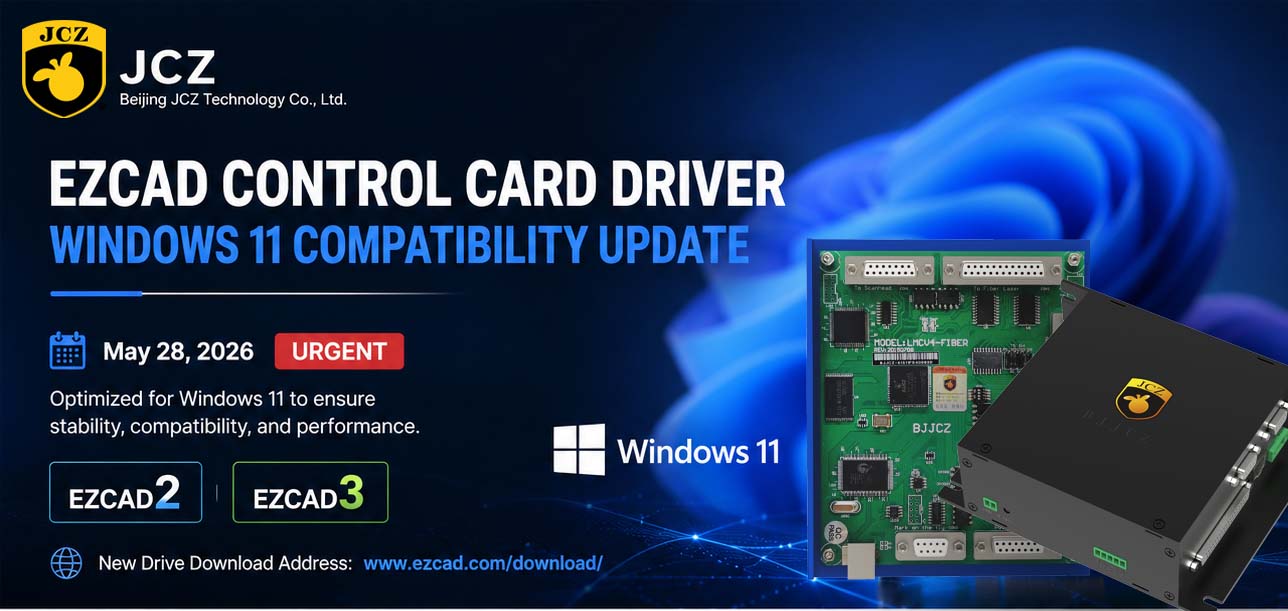
OFFICIAL DRIVER UPDATE NOTICE

Top Factors That Affect Marking Quality in Handheld Fiber Laser Systems

Meet JCZ at Laser World of Photonics India 2026 in Bengaluru
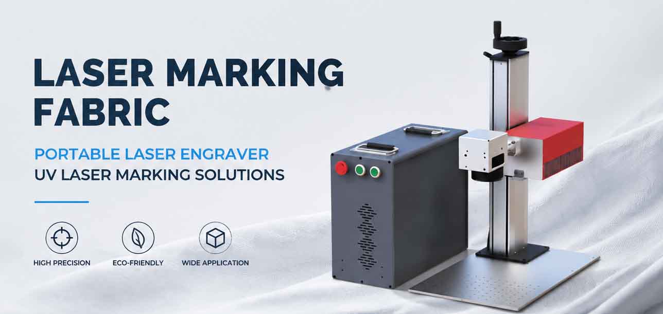
Laser Marking Fabric with Portable Laser Engraver: Advanced UV Laser Marking Solutions for Modern Manufacturing
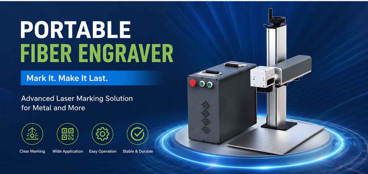
Laser Machine for Marking: The Ultimate Guide to Portable Fiber Engravers & MOPA Color Laser Marking

Laser Cleaning Machine for Wood: The Ultimate Guide to Safe, Precise & Eco-Friendly Wood Surface Cleaning