Picosecond Laser Specifications
| Product Model | IR Picosecond-1064-15 | IR Picosecond-1064-30 | IR Picosecond-1064-50 |
| Center Wavelength | 1064±0.5 nm | ||
| Power | 15 W@100 kHz | 30 W@100 kHz | 50 W@100 kHz 50 W@50 kHz |
| Repetition Rate | 1 HZ~1 MHZ | ||
| Pulse Energy | 150 μJ | 300 μJ | 500 μJ@Burst 1 1.0 mJ@Burst 2 |
| Power Stability | <1% (8 hours, RMS) | ||
| Pulse Duration | ~10 ps | ||
| Beam Quality | TEMoo, M²≤1.2 | TEMoo, M²≤1.3 | |
| Beam Circularity | >90% | ||
| Beam Diameter | ~2 mm | ~3 mm | |
| Burst Mode | 1~5 | ||
| Dimensions | 600*288*132.5 mm³ | 800*332*132.5 mm³ | |
| Trigger Mode | PSO, POD, Gate mode, and TTL trigger | ||
| External Power Control | 0~5 V | ||
| Warm-up Time | 15 min | ||
| Electrical Requirements | AC 100~240 V/50~60 Hz | ||
| Environment Humidity | <60% RH@25℃ | ||
| Environment Temperature | 22-30 °C | ||
| Cooling | Water cooling | ||
IR Picosecond Laser Specifications
| Product Model | IR Picosecond Laser-1064-80 | IR Picosecond Laser-1064-200 | IR Picosecond Laser-1064-500 |
| Center Wavelength | 1064±0.5 nm | ||
| Power | 80 W@Burst 5@20 kHz | 200 W@1 MHz | 500 W@3 MHz |
| Repetition Rate | 1 Hz~2 MHz | 1 Hz-6 MHz | |
| Pulse Energy | 4 mJ@Burst 5@20 kHz | 200 μJ | 150 μJ |
| Power Stability | <1%(8 hours, RMS) | ||
| Pulse Duration | -15 ps | -10 ps | -10 ps |
| Beam Quality | TEMoo, M²≤1.3 | ||
| Beam Circularity | >90% | ||
| Beam Diameter | -3 mm | ||
| Burst Mode | 5~6 | ||
| Dimensions | 800*364*140 mm³ | 800*420*139.5 mm³ | 980*560*153 mm³ |
| Trigger Mode | PSO、POD、Gate mode,and TTL trigger | ||
| External Power Control | 0-5 V | ||
| Warm-up Time | 15 min | ||
| Electrical Requirements | AC 100-240 V/50-60 Hz | ||
| Environment Humidity | <60% RH@25°C | ||
| nvironmentTemperature | 22-30℃ | ||
| Cooling | Water cooling | ||
Green Picosecond Laser Specifications
| Product Model | Green Picosecond Laser-532-6 | Green Picosecond Laser-532-30 | Green Picosecond Laser-532-90 | Green Picosecond Laser-532-200 |
| Center Wavelength | 532±0.5 nm | |||
| Power | 6 W@100 kHz | 30 W@100 kHz | 90 W@300 kHz | 200 W@1 MHz |
| Repetition Rate | 1 Hz-1 MHz | 1 Hz-2 MHz | ||
| Pulse Energy | 60 μJ | 300 μJ | 300 μJ | 200 μJ |
| Power Stability | <1%(8 hours, RMS) | |||
| Pulse Duration | -7ps | <15ps | ||
| Beam Quality | TEMoo, M²≤1.1 | TEMoo, M²≤1.2 | TEMoo, M²≤1.3 | |
| Beam Circularity | >90% | |||
| Beam Diameter | ~1.5mm | ~2mm | ||
| Burst Mode | 1-5 | |||
| Dimensions | 600*288*132.5 mm³ | 800*364*140 mm³ | 800*420*139.5 mm³ | 980*560*153 mm³ |
| Trigger Mode | PSO、POD、Gate mode,and TTL trigger | |||
| External Power Control | 0-5 V | |||
| Warm-up Time | 15 min | |||
| Electrical Requirements | AC 100-240 V/50-60 Hz | |||
| Environment Humidity | <60% RH@25°C | |||
| nvironmentTemperature | 22-30℃ | |||
| Cooling | Water cooling | |||
UV Picosecond Laser Specifications
| Product Model | UV Picosecond Laser-355-5 | UV Picosecond Laser–355-20 | UV Picosecond Laser–355-30 | UV Picosecond Laser–355-60 | UV Picosecond Laser–355-100 |
| Center Wavelength | 355士0.5 nm | ||||
| Power | 5 W@300 kHz | 20 W@1 MHz | 30 W@1 MHz | 60 W@1 MHz | 100 W @3 MHz |
| Repetition Rate | 1 Hz~2 MHz | 1 Hz~6 MHz | |||
| Pulse Energy | 15 μJ | 60-100 μJ | 30 uJ | ||
| Power Stability | <1%(8 hours, RMS) | ||||
| Pulse Duration | ~7 ps | ||||
| Beam Quality | TEMoo, M²≤1.2 | TEMoo, M²≤1.3 | |||
| Beam Circularity | >90% | ||||
| Beam Diameter | ~2mm | ~3mm | |||
| Dimensions | 600*288*132.5 mm³ | 800*332*132.5 mm³ | 800*364*140 mm³ | 980*560*153 mm³ | |
| Trigger Mode | PSO、POD、Gate mode,and TTL trigger | ||||
| External Power Control | 0-5 V | ||||
| Warm-up Time | 15 min | ||||
| Electrical Requirements | AC 100-240 V/50-60 Hz | ||||
| Environment Humidity | <60% RH@25°C | ||||
| nvironmentTemperature | 22-30℃ | ||||
| Cooling | Water cooling | ||||
A picosecond laser is an ultrafast laser that emits pulses with a duration measured in trillionths of a second — typically between 1 and 15 picoseconds (10⁻¹² seconds). This pulse width is significantly shorter than nanosecond lasers (10⁻⁹ s) and substantially longer than femtosecond lasers (10⁻¹⁵ s), placing picosecond lasers in a uniquely practical position for industrial applications: they minimize the heat-affected zone (HAZ) far better than nanosecond lasers while remaining more affordable, robust, and higher in average power than femtosecond systems.
EZCAD’s high-power picosecond laser source series delivers ultrafast, ultrashort pulses across three wavelengths — infrared (1064nm, up to 500W), green (532nm, up to 200W), and ultraviolet (355nm, up to 100W) — for demanding industrial micromachining, semiconductor scribing, display panel cutting, and precision microstructuring. Built on a hybrid fiber and solid-state amplification architecture, these industrial picosecond lasers combine the stability of fiber delivery with the high peak power of solid-state gain to meet 7×24 production requirements.
A picosecond laser source should not be selected by average power alone. For most applications, the correct sequence is:
material and process → wavelength → required pulse energy and repetition rate → average power → beam delivery and optical compatibility → integration requirements.
Choose the Picosecond Laser Source by Wavelength First
Wavelength determines how effectively the workpiece interacts with the laser and also affects focusing optics, achievable spot size and the complete beam-delivery configuration.
The same material may require different wavelengths for different processes. For example, cutting, surface ablation, coating removal and internal modification of glass are not the same process. We therefore recommend selecting wavelength from the actual material stack and required processing result rather than from the material name alone.
1064nm IR Picosecond Laser — Prioritize Power and Throughput
The 1064 nm IR range provides the highest available average power in this series, with listed models from 15 W up to 500 W.
IR is normally the first wavelength to evaluate when:
- the target material absorbs sufficiently at 1064 nm;
- production throughput is more important than obtaining the smallest possible optical spot;
- high pulse energy or high average power is required;
- the existing machine architecture is already based on 1064 nm optics.
Typical processes to evaluate include metal and ceramic micromachining, thin-film removal, drilling, surface texturing, scribing and other high-throughput precision-ablation processes.
For materials with poor IR absorption, however, increasing average power is not always the correct solution. A green or UV wavelength may achieve the required process with a different energy density and a smaller optical spot.
532nm Green Picosecond Laser — Consider It for Copper and Fine Microprocessing
The green series covers listed power levels from 6 W to 200 W.
Green wavelengths are often selected when a material absorbs visible green energy more effectively than near-IR energy. Industrial ultrafast-laser suppliers specifically use green wavelengths for materials including copper, polymers and ceramics, and the shorter wavelength can also support a smaller focused spot for a given optical configuration.
Processes worth evaluating with a 532 nm picosecond laser include:
- copper and thin-metal processing;
- PCB and FPC microprocessing;
- semiconductor and electronic-material processing;
- solar-cell scribing;
- surface texturing;
- fine drilling and ablation where IR does not provide the required process window.
The final decision should still be based on sample testing because coating, thickness, alloy composition, scan speed and target feature geometry can change the optimum wavelength.
355nm UV Picosecond Laser — Prioritize Fine Features and Sensitive Materials
The UV series includes listed 5 W, 20 W, 30 W, 60 W and 100 W models.
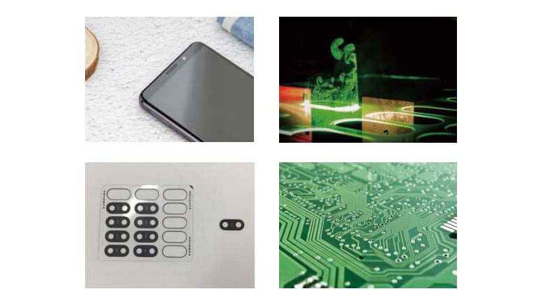
Shorter UV wavelengths can provide a smaller diffraction-limited spot and are more readily absorbed by some polymers, semiconductor materials and multilayer electronic substrates. UV ultrafast lasers are therefore widely evaluated for polymer cutting, wafer dicing, PCB cutting and drilling, and OLED processing.
A 355 nm picosecond laser source should be considered when:
- the required feature size is difficult to achieve with IR;
- the material is sensitive to excessive thermal input;
- the process involves thin polymers, coatings or electronic material stacks;
- fine ablation or high edge-quality processing is more important than simply maximizing average power.
UV is not automatically the best wavelength for every transparent material. For glass and other brittle transparent substrates, the optimum wavelength depends on whether the process uses surface absorption, ablation, modification or another interaction mechanism. A material test is recommended before the final laser configuration is fixed.
Picosecond Laser Source Model Range
The current EZCAD series provides a broad wavelength and power range for different levels of precision processing and throughput.
IR Picosecond Laser Sources
| Wavelength | Listed Power Models | Maximum Listed Repetition Rate | Typical Pulse Duration | Cooling |
|---|---|---|---|---|
| 1064 ±0.5 nm | 15 / 30 / 50 / 80 / 200 / 500 W | Up to 6 MHz, model-dependent | Approximately 10–15 ps, model-dependent | Water cooling |
Green Picosecond Laser Sources
| Wavelength | Listed Power Models | Maximum Listed Repetition Rate | Typical Pulse Duration | Cooling |
|---|---|---|---|---|
| 532 ±0.5 nm | 6 / 30 / 90 / 200 W | Up to 2 MHz, model-dependent | Picosecond range, model-dependent | Water cooling |
UV Picosecond Laser Sources
| Wavelength | Listed Power Models | Maximum Listed Repetition Rate | Typical Pulse Duration | Cooling |
|---|---|---|---|---|
| 355 ±0.5 nm | 5 / 20 / 30 / 60 / 100 W | Up to 6 MHz, model-dependent | Approximately 7 ps | Water cooling |
Published specifications also list beam quality values in approximately the M² ≤1.1–1.3 range depending on model, beam circularity above 90%, and model-dependent beam diameters of approximately 1.5–3 mm.
Because pulse energy changes with operating frequency and operating mode, confirm the required pulse energy at your actual repetition rate rather than comparing only maximum average power.
How to Select Average Power, Pulse Energy and Repetition Rate
These three parameters must be evaluated together.
For single-pulse operation:
Average Power ≈ Pulse Energy × Repetition Rate
This means two 100 W laser sources can produce very different material interactions.
A lower repetition rate with higher energy per pulse generally produces a higher fluence at the same focused spot, while a higher repetition rate can increase pulse overlap and processing throughput.
The correct choice depends on:
- ablation threshold of the material;
- required feature size;
- focused spot diameter;
- scan speed;
- pulse overlap;
- required removal depth;
- allowable thermal accumulation;
- cycle-time target.
Do Not Select a Picosecond Laser by Wattage Alone
A 200 W source is not automatically twice as suitable as a 100 W source.
If the extra power is available mainly at a much higher repetition rate, the energy of each pulse may not increase proportionally. Conversely, a lower-power model operating at a lower frequency may provide higher energy per pulse for drilling or localized ablation.
When requesting a quotation, specify both the required average power and the process conditions under which the power is needed.
Understand Burst Mode Separately
Burst operation sends a group of closely spaced pulses instead of treating every processing event as one isolated pulse.
Burst mode can change:
- total energy delivered to one location;
- ablation efficiency;
- material-removal behavior;
- thermal accumulation;
- surface finish.
The EZCAD series provides burst operation on selected configurations. The required burst count and energy distribution should be verified for the selected model and application rather than compared only by total burst energy.
Application-to-Laser Selection
The following table is a selection starting point rather than a substitute for process testing.
| Application | First Wavelength to Evaluate | Main Selection Reason | Parameters to Confirm |
|---|---|---|---|
| PCB / FPC cutting and drilling | Green or UV | Fine features and material absorption | Pulse energy, spot size, layer stack |
| Copper foil processing | Green | Better absorption can improve the process window | Thickness, coating, pulse energy |
| OLED / display processing | UV or Green | Fine features and reduced thermal input | Edge quality, scan speed, spot |
| Semiconductor wafer processing | Green or UV | Fine ablation and substrate interaction | Wafer material, coating, kerf |
| Ceramic drilling / scribing | IR or Green | High pulse energy or material-dependent absorption | Hole diameter, depth, taper |
| Thin-film ablation | IR / Green / UV | Strongly dependent on film/substrate pair | Selectivity and substrate damage |
| Metal micromachining | IR first | High available average power | Alloy, feature size, removal rate |
| Polymer processing | Green or UV | Shorter wavelengths can improve absorption | Melting, discoloration, edge quality |
| Glass processing | Application-dependent | Different processes use different interaction mechanisms | Glass type, thickness, process mechanism |
| Sapphire / brittle material processing | Application-dependent | Requires balancing energy, cracking and throughput | Edge quality and required depth |
For unfamiliar materials or multilayer structures, process testing is more reliable than choosing a wavelength from a generic material chart.
OEM Integration and Optical Compatibility
A picosecond laser source is only one part of the processing system. Before the laser model is finalized, the scanner, focusing optics, motion controller and cooling system must also be checked.
Trigger and Process Control
The current series lists:
- PSO;
- POD;
- Gate mode;
- TTL triggering;
- 0–5 V external power control.
These options make the source suitable for integration with automated motion and scanning systems, but the final trigger architecture should be selected according to the machine-control strategy.
For high-speed scanning or on-the-fly processing, confirm:
- trigger timing;
- pulse synchronization;
- scanner speed;
- pulse spacing on the workpiece;
- acceleration and corner behavior;
- required pulse energy at changing speeds.
Galvo Scanner Compatibility
Check the scanner for:
- wavelength coating;
- input aperture;
- beam diameter;
- peak-power capability;
- required scan speed.
A galvo designed for 1064 nm should not automatically be reused with a 355 nm source without checking its optical coating and specifications.
F-Theta Lens Compatibility
The F-theta lens must match:
- 1064 / 532 / 355 nm wavelength;
- scanner aperture;
- incoming beam diameter;
- required field size;
- desired focused spot;
- optical power density.
EZCAD also supplies wavelength-specific F-theta scanning lenses for industrial laser systems. The available lens range includes UV, green and IR configurations.
Cooling and Installation
The listed picosecond laser source models use water cooling.
Before machine design is finalized, confirm:
- laser dimensions for the selected model;
- chiller capacity;
- coolant temperature range;
- hose and connection layout;
- ambient temperature and humidity;
- service clearance around the laser.
Model dimensions increase with power level, so the mechanical layout should be based on the selected model drawing rather than on one generic enclosure size.

What Changes the Picosecond Laser Source Quotation?
Picosecond laser source pricing should be compared by configuration rather than by wattage alone.
The main quotation factors normally include:
Wavelength
IR, green and UV sources use different optical configurations. Harmonic-generation requirements and wavelength-specific optics can change the system configuration and cost.
Average Power and Pulse-Energy Range
Higher average power does not describe the complete laser requirement. A system requiring both high average power and high pulse energy at a specified frequency can require a different configuration from a system optimized mainly for high-frequency scanning.
Pulse-Control Requirements
Burst operation, POD, PSO and other synchronization requirements can influence the required control configuration.
Beam and Process Requirements
Applications requiring tighter beam-quality, stability or integration specifications may require a different configuration or additional validation.
Cooling and Beam Delivery
The chiller, optical components, beam expander, scanner and focusing lens should be included when comparing complete machine-integration cost.
Quantity and OEM Requirements
For machine builders, quotation requirements may also depend on order quantity, integration documentation, configuration consistency and project-specific technical support.
MOQ and lead time should therefore be confirmed for the exact model rather than assumed from the laser family.
Common Specification Mistakes When Buying a Picosecond Laser Source
Mistake 1: Selecting Only by Average Power
Average power does not show how much energy reaches the workpiece in each pulse.
Always compare average power together with:
- repetition rate;
- pulse energy;
- pulse duration;
- operating mode.
Mistake 2: Assuming Maximum Power Is Available at Every Frequency
Rated output is normally specified at defined operating points.
Ask for the required power and pulse energy at your intended repetition rate.
Mistake 3: Comparing Burst Energy Directly with Single-Pulse Energy
A burst contains multiple pulses.
Confirm:
- number of pulses;
- total burst energy;
- energy per sub-pulse;
- burst repetition rate.
Mistake 4: Choosing UV Simply Because the Feature Is Small
UV can provide a smaller optical spot, but throughput, material behavior, optical cost and required power must also be considered.
Mistake 5: Ignoring the Existing Optical System
Changing from IR to green or UV can require changes to:
- galvo mirrors;
- F-theta lens;
- beam expander;
- protective window;
- diagnostic optics.
Mistake 6: Selecting a Laser from the Material Name Alone
“Glass,” “ceramic,” “copper” or “PCB” is not enough information.
The supplier should know the exact material grade, thickness, coating or layer stack and required process result.
Request a Sample Test or Technical Consultation
Investing in a picosecond laser system is a critical decision. We invite you to verify the results on your specific material.
- Free Sample Testing: Send us your material, and our lab will process it with our IR, Green, or UV laser source to show you the quality.
- OEM Integration: Discuss your machine building requirements with our engineers.
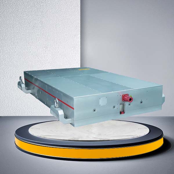
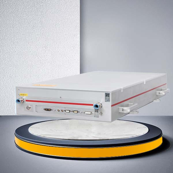
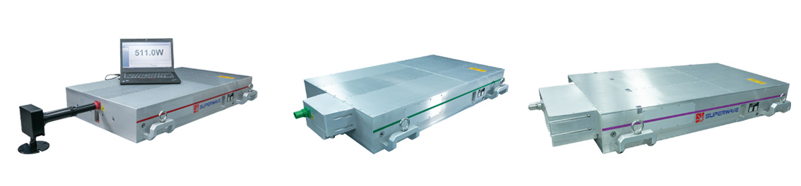
Product Pictures
IR picosecond lasers Green picosecond lasers UV picosecond lasers
Product Applications