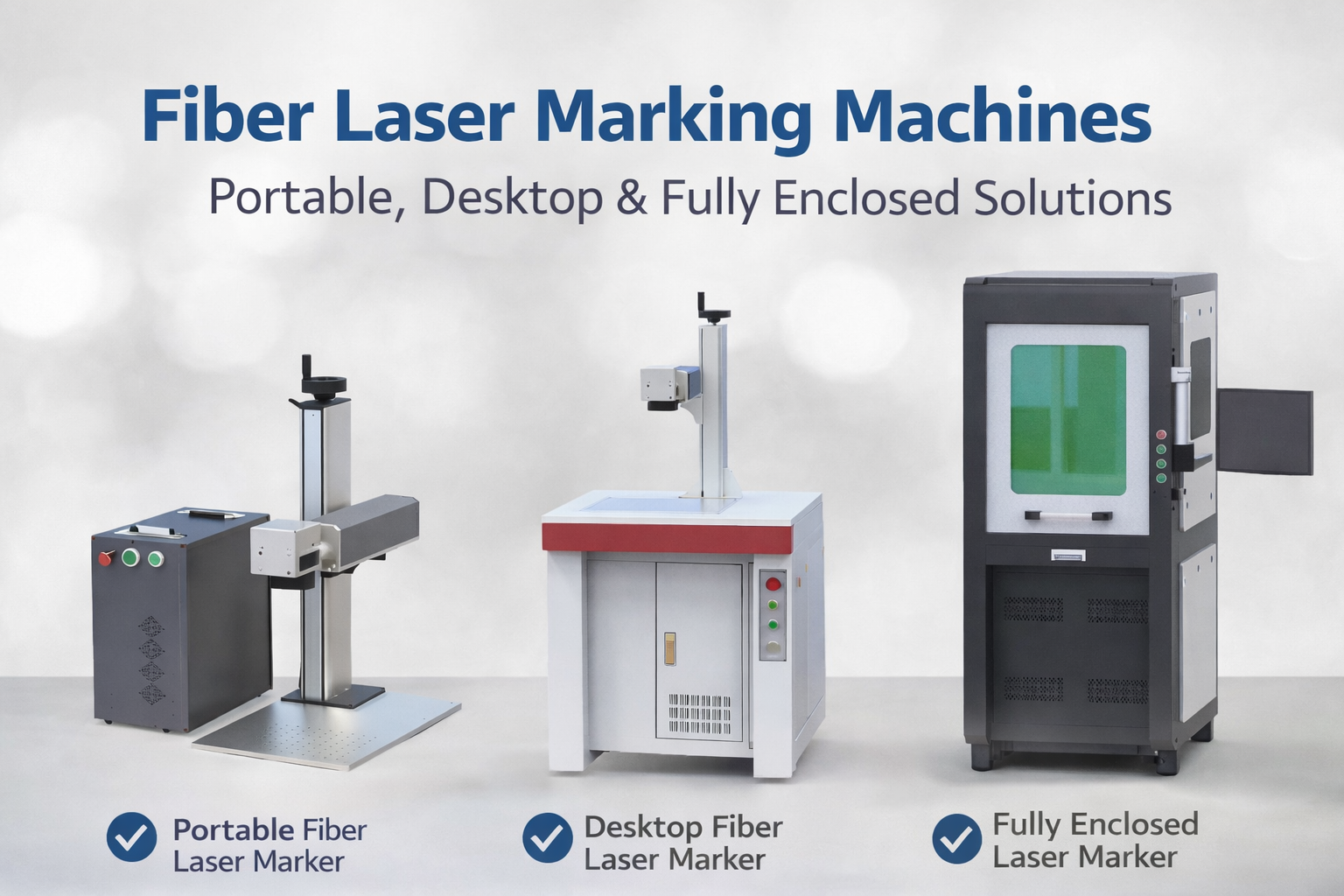
Tips for Reducing Setup Time in Enclosed Laser Marking Cells
Every minute a laser marker sits idle between batches is a minute of lost capacity. For contract manufacturers and OEMs running high-mix production, setup time inside an enclosed cell can eat up 30 % of a shift before a single good part is marked. The safety housing that protects operators also slows them down—doors, interlocks, and awkward access conspire to turn a simple job change into a 45‑minute ritual. The good news is that most of that time consists of activities you can eliminate, offload, or parallelise without compromising safety. The following tips draw on real‑world factory experience with the EZCAD control ecosystem and the hardware‑agnostic principles of SMED (Single‑Minute Exchange of Die). Whether you run a single 20 W fibre laser or a fleet of flying‑marking systems, these methods will help you push setup time below 15 minutes and keep your beam firing on parts, not thin air.
Why Setup Time Hurts More Inside an Enclosed Cell
An open‑gantry laser lets an operator walk up, slide a fixture in, load a file, and start marking. An enclosed Class‑1 cell requires door monitoring, safe‑stop verification, fume extraction checks, and often internal manual adjustments performed through glove ports or after bypassing—under strictly controlled work procedures—the safety circuit. Every extra step that involves a physical movement inside the housing multiplies the minutes.
Industry data collected from laser job shops shows that changeover inside a safety‑enclosed marking cell typically takes between 30 and 45 minutes. That figure aligns with the early findings of Shingo’s SMED research, which revealed that internal setup activities—those that can only be performed while the machine is stopped—account for roughly 70 % of total changeover time. Inside a laser cell, “internal” often means crawling into the enclosure, repositioning fixtures, jogging the galvo, and running test marks. Each of those activities is not only slow but also introduces an opportunity for alignment drift and operator error.
A more strategic view treats the enclosure not as a barrier but as a process‑discipline enabler. The key is to push as many setup tasks as possible outside the cell—onto the engineering workstation—so that when the operator does open the door, the only job left is to swap a pre‑qualified nest and press “start.”
Deconstructing Your Current Setup Sequence
Before you can shrink setup time you have to see it. Grab a stopwatch and record every event from the last good part of the previous order to the first good part of the next. Be obsessive: clip‑board logging by a supervisor often misses the 40‑second walk to the PC, the three‑minute wait for a file to load, or the two test cycles that were needed because the first mark drifted by 0.3 mm.
A typical breakdown from a mid‑volume automotive component line looks like this:
| Setup Activity | Traditional Time (min) | Optimised Time (min) | Levers for Reduction | |—————-|————————|———————-|———————-| | Remove/install workholding nest | 12 | 4 | Quick‑change baseplate, pneumatic clamping | | Load & parameterise marking file | 10 | 2 | Template library, auto‑scaling in EZCAD3 | | Verify safety‑circuit function | 5 | 1 | Automatic interlock diagnostics via software | | Adjust focal height & alignment | 8 | 3 | Motorised Z‑axis with saved presets | | Prove‑out & first‑article inspection | 10 | 5 | Dry‑run preview, camera‑assisted positioning | | Total | 45 | 15 | |
The table reveals that file loading and parameter tuning alone eat up almost a quarter of the baseline time. This is where the right laser‑control software becomes a hard‑dollar productivity tool.
Let the Software Carry the Parametric Load
An enclosed cell’s physical constraints mean you want the operator to touch the PC more than the machine. That makes the marking engine—the software—the central lever for setup reduction. A factory that upgrades to an integrated Laser Software platform gains the ability to store, recall, and auto‑apply complete marking “recipes” that bundle layout, laser parameters, scanhead corrections, and axis positions into a single loadable object.
Template libraries eliminate point‑and‑click fatigue
When every new part starts from a blank canvas, operators redo the same micro‑decisions—selecting wavelength parameters, tweaking hatch spacing, setting speed and frequency—dozens of times a week. A properly built template library inside Ezcad2 Software or its successor cuts that to zero. You define one golden template per material group (e.g., “Al6082_black_anneal_20W”) and lock the critical fields by user permission. On the shop floor, the operator picks the template, verifies the auto‑loaded settings on a preview screen, and proceeds. Time saved: 6–8 minutes per changeover.
Fast processing engines shorten the “wait for the screen” gap
Perception of delay is as important as the delay itself. The completely new architecture of Ezcad3 Software was designed to accelerate data processing for high‑precision tasks. In practical terms, complex vector‑heavy files that used to take 5–8 seconds to render and compile on legacy controllers now appear almost instantly. When you multiply that by the 10–15 file‑load events a typical day‑shift operator performs, the cumulative time saving often surpasses 20 minutes per shift. That gain comes before you touch a fixture.
SDK integration puts the ERP in charge
If your production volume justifies it, take the human out of the recipe‑selection loop entirely. The EZCAD2 and EZCAD3 SDKs expose marking functions—including file loading, laser parameter setting, and event logging—through a well‑documented API. An MES or ERP system can read a barcode on the incoming work tray, query the database, and push the correct marking file and focal offset directly to the laser controller. This kind of integration routinely reduces the setup‑related software interaction to under 30 seconds, and it eliminates data‑entry errors that lead to scrap and rework. According to a study by the International Society of Automation (ISA‑95 working group), automated recipe management can cut parameter‑adjustment time by 40 % to 60 % across discrete‑part manufacturing cells.
Standardise the Physical Interface: Fixtures, Focal Planes, and Flying Optics
The mark‑on‑the‑fly capability that JCZ control boards support reveals another opportunity. When the laser can fire accurately while the galvo tracks a moving part, you no longer need to fixture every variant in a static clamp; a simple rail or belt system delivers parts past the scanhead, and the software compensates for position drift. This shifts the setup discussion from “how fast can I clamp it?” to “how fast can I register it?”
For parts that must remain stationary, invest in a modular baseplate with kinematic coupling points. A standard mating plate on the bottom of every fixture nest lets an operator drop it in, engage two levers, and achieve repeatable positioning within a typical tolerance band of ±0.05 mm—sufficient for laser marking, where the galvo’s field correction can handle residual misalignment. Dowel‑pin‑based systems regularly reduce fixture change time from 12 minutes to below 4 minutes, as shown in the earlier table.
Focal adjustment deserves equal attention. A motorised Z‑axis driven directly by the EZCAD software can store a digital preset tied to each template. When the template loads, the Z stage moves to the saved height. Operators no longer eyeball a ruler or fiddle with a manual dovetail slide. Multi‑axis control boards from JCZ already support closed‑loop motion commands; enabling this feature eliminates the 5–8 minutes of focus drifting that commonly plague manual setups.
Tame the Safety Loop Without Adding Minutes
Safety‑circuit verification must never be rushed, but it can be streamlined. IEC 60825‑1—the international standard for laser product safety—mandates that an enclosure’s protective housing and interlocks function reliably, requiring the laser to shut off when a door is opened. Many installations still rely on a manual push‑button test that forces the operator to open the door, trip the interlock, confirm the shutter closure, reset, and re‑close. That sequence can chew up 4–5 minutes.
Modern galvo controllers and the EZCAD platform support soft‑interlock diagnostics that run a self‑check cycle on each power‑up. The system verifies the signal chain—door sensor, relay, laser‑enable line—within the boot sequence and logs the result. If the diagnostic passes, the operator sees a “Safety System OK” flag and never has to touch the door for testing. When CE‑marked subsystems are used, this approach satisfies the performance‑level requirements of EN ISO 13849‑1 while cutting the routine safety check down to approximately 60 seconds.
Fly Before You Mark: Preview and Dry‑Run Validation
Every mark that fails the first‑article inspection adds 8–10 minutes of rework, plus the cost of the scrapped component. The EZCAD software family includes a “red‑light pointer” preview mode that projects the intended mark outline onto the part using a low‑power guide beam. With the enclosure door still closed—and the interlocks satisfied by the safety system—the operator can jog the galvo and confirm that the layout fits within the part boundaries. This external‑to‑the‑cell check avoids a door‑open intervention and catches alignment errors early.
For high‑volume lines, consider a fixed‑focus USB camera aligned coaxially with the laser beam. The image is fed into the software, allowing an overlay of the marking file on a live picture of the part. Once the correlation is set for a part number, subsequent setups recall it. The alignment time drops from several minutes of manual jogging to a single‑click confirm action. Measurements taken from an electronics‑housing marking line in Germany documented a reduction of first‑article alignment from 9 minutes to 2.5 minutes after adopting this technique—a 72 % improvement.
Monitor, Measure, and Attack the Next Bottleneck
Setting up faster is not a one‑time project but a continuous loop of observation and refinement. The EZCAD software’s event‑logging capability can be harnessed to time‑stamp key events: file load, door open, door close, first laser‑on, and job‑complete. Feeding that log into a simple dashboard shows daily setup‑time trends and exposes drift. If Monday’s setup took 14 minutes and Thursday’s took 18 minutes, the data prompts a targeted investigation—perhaps a fixture locating pin has worn, or a new operator needs a refresher on the quick‑change sequence.
Once you have a few weeks of data, set a public target. Posting a chart near the cell that shows “Average Setup Time: 12 min — Goal: 10 min” creates shared accountability. Teams that see the number every day tend to shave off the small wastes: the extra walk to the filing cabinet, the missing hex key, the file named “temp_final_v2” that someone has to decode. Lean manufacturing literature consistently reports that visible measurement alone accounts for a 10–15 % additional time reduction beyond the initial process fixes.
Frequently Asked Questions
What is the minimum safety interlock requirement for an enclosed laser marking cell?
EN ISO 13849‑1 typically demands a performance level of at least “c” or “d” depending on the risk assessment, with a hardware‑based safety relay. The laser must stop emission within milliseconds of the door opening, as defined by the IEC 60825‑1 standard. Modern controllers like those compatible with EZCAD systems can integrate these signals without extra PLC hardware.
Can Ezcad2 and Ezcad3 templates be shared across multiple machines?
Yes. The template file format is portable between machines running the same software generation. This allows an engineer to prepare and validate a template offline on a programming station and then push it to the shop‑floor PC via a network share, ensuring consistency and avoiding on‑machine trial‑and‑error.
Does reducing setup time compromise marking quality?
When standardised templates and pre‑qualified fixtures are used, quality actually improves. The process becomes repeatable rather than dependent on an operator’s skill that day. A NIST study on manufacturing repeatability (NISTIR 6257) found that standardisation reduces process variance by up to 60 % compared with manual setup, directly lowering the defect rate.
Making the First Move Tomorrow
Reducing setup time in an enclosed laser marker isn’t about spending a fortune on automation; it’s about methodically removing the seconds and minutes that don’t add value. Pick one cell, log the next ten changeovers, and circle the two biggest slices of the pie. If they’re software‑related, start building a template library in EZCAD2 or EZCAD3 this week. If they’re hardware‑related, sketch a quick‑change baseplate and order the dowel pins. The payback is immediate: a machine that once sat idle for 45 minutes between jobs and is now ready in 12 minutes gives you an extra three hours of beam‑on time in a single shift. Multiply that across a handful of cells, and you’ll produce more good parts without buying a single new laser.
The tools are already inside the controller you’re using. The enclosure that once felt like an obstacle becomes a predictable, safe framing for a tightly orchestrated process. All you need to supply is the discipline to measure, standardise, and then automate the last repetitive motion.

OFFICIAL DRIVER UPDATE NOTICE

Top Factors That Affect Marking Quality in Handheld Fiber Laser Systems

Meet JCZ at Laser World of Photonics India 2026 in Bengaluru
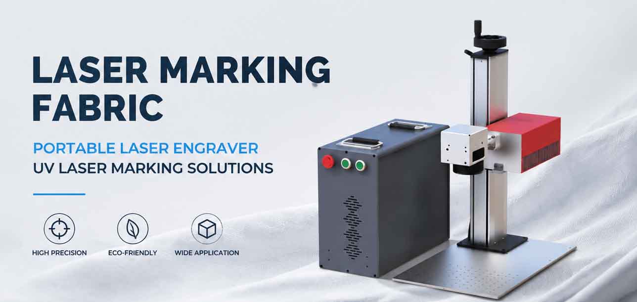
Laser Marking Fabric with Portable Laser Engraver: Advanced UV Laser Marking Solutions for Modern Manufacturing
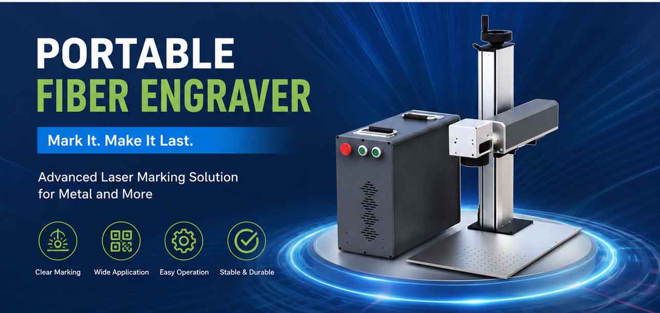
Laser Machine for Marking: The Ultimate Guide to Portable Fiber Engravers & MOPA Color Laser Marking

Laser Cleaning Machine for Wood: The Ultimate Guide to Safe, Precise & Eco-Friendly Wood Surface Cleaning