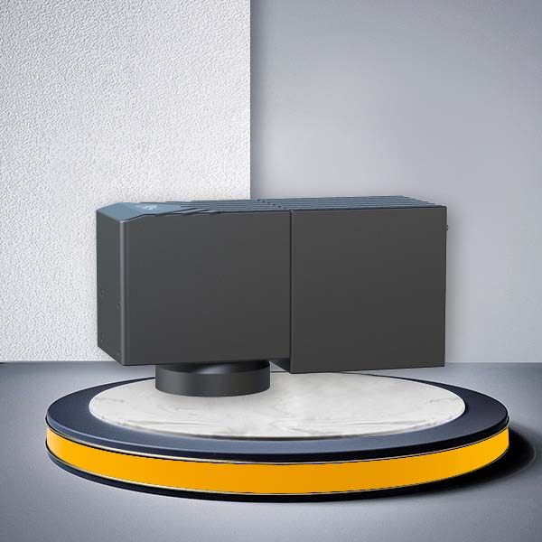
| Configurations | ||||
| Scanner | Input Diameter | 10 mm | ||
| Tracking Error | 0.25 ms | |||
| Marking Speed | 4000 mm/s | |||
| Positioning Speed | 10000 mm/s | |||
| 1% Full Scale | ≤ 0.4 ms | |||
| Repeatability | < 8 μrad | |||
| Gain Drift | < 50 ppm/K | |||
| Offset Drift | < 15 μrad/K | |||
| Drift Over 8h | < 0.3 mrad | |||
| Nonlinearity | < 3.5 mrad/44° | |||
| Interface | XY2 – 100 | |||
| Scan Angle | ± 0.35 rad | |||
| Optical | Wavelength | 1064 nm | 532 nm | 355 nm |
| Dynamic Zoom System Parameters | Input Aperture | 7 mm | 7 mm | 3 mm |
| Beam Ratio | 1.4 | 1.4 | 3 | |
| Marking Area | ± 30 mm (F254-174lens) | ±7 mm (F165-115 lens) | ± 15 mm (F254-175lens) | |
| Focus Range | 1500 (Replaceable F-θ lens) | 100 (Replaceable F-θ lens) | 150 (Replaceable F-θ lens) | |
| Basic | Power | ± 15 V DC, 5 A | ||
| Working Temp | 25 ± 10°C | |||
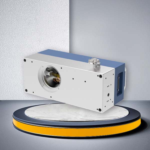
G3-3D 3D Galvo Scanner for Curved Surface Laser Processi
G3 3D adopts the third axis module developed by JCZ, which has faster response speed, faster zoom and more stable. The system has strong anti-interference ability, high reliability, good linearity, high repetition precision and short response time. The system adopts integral structure with small volume, light weight and good sealing performance to ensure the stability under long working conditions. G3 3D is suitable for complex curved surface processing, 3D deep carving, high power cutting, drilling, laser micro processing, 3D printing, etc. According to the different wavelength and mirror size, it can process various materials such as metal, leather, rubber, wood, bamboo products, ceramic tile, plastic, marble, jade and other materials.
Why Use a 3D Galvo Scanner Instead of a Standard 2D Galvo?
A conventional 2D galvo scanner controls laser movement in the X and Y directions and is suitable when the processing surface remains close to one focal plane.
A 3D galvo scanner head adds dynamic focus control along the Z direction. This allows the focal position to change while the beam is scanning, making it better suited to workpieces with varying height or complex geometry.
| Processing Requirement | 2D Galvo Scanner | G3-3D 3D Galvo Scanner |
|---|---|---|
| Flat surface marking | Suitable | Suitable |
| Curved surface processing | Limited | Suitable |
| Stepped surfaces | Requires additional focusing or movement | Suitable |
| Components with changing height | Limited | Dynamic Z focus |
| Deep engraving | Process dependent | Better suited to dynamic depth processing |
| 3D surface marking | Limited | Designed for this requirement |
| Dynamic focal adjustment | No dedicated Z focus | Yes |
| Complex XYZ processing | Limited | Supported with compatible control system |
For standard flat marking applications, you can also evaluate JCZ 2D Galvo Scanners.
Dynamic Focus for Curved and Variable-Height Surfaces
The main reason to choose the G3-3D is not simply to add a third axis. It is to maintain the required laser focal position when the processing surface changes in height.
Typical workpiece geometries include:
- Curved housings – Keep the laser focused as the surface height changes across the part.
- Cylindrical and partially cylindrical components – Process curved sections without relying only on a fixed focal plane.
- Stepped parts – Move between different height levels during one processing job.
- Sloped surfaces – Compensate for gradual changes in surface height.
- Domed components – Follow convex or concave surface geometry.
- Molds and tooling – Support engraving where the processing depth or surface position changes.
- Raised and recessed features – Process structures that cannot be covered effectively with a single fixed focus.
- Irregular industrial components – Suitable for projects requiring XYZ focus coordination.
Typical applications include curved-surface marking, 3D engraving, deep engraving and precision laser processing.
Post-Focusing 3D Galvo Architecture
The G3-3D uses a post-focusing architecture with a replaceable F-theta lens.
The third-axis module adjusts the focus position while the X/Y galvanometer mirrors control the laser path across the workpiece.
JCZ currently specifies different Z adjustment ranges according to wavelength and lens configuration:
| Wavelength | Typical Optical Direction | Published Z / Zoom Range |
| 1064nm | Fiber laser | ±30 mm with F254-174 lens |
| 532nm | Green laser | ±7 mm with F165-115 lens |
| 355nm | UV laser | ±15 mm with F254-175 lens |
Actual usable processing range depends on the lens, beam diameter, laser source, surface geometry and required spot quality.
Post-focusing 3D systems are particularly useful when you need Z adjustment while retaining an F-theta-based optical architecture. RAYLASE uses a similar general concept in its FOCUSSHIFTER RD-14, combining an F-theta lens with dynamic optical Z adjustment for processing workpieces with different height levels.

Select the G3-3D by Laser Wavelength
The optical configuration of a 3D galvo scanner head must match the laser wavelength. G3-3D currently provides configurations for 1064 nm, 532 nm and 355 nm.
| Laser Wavelength | Typical Laser Direction | Current G3-3D Published Configuration | Typical Applications |
|---|---|---|---|
| 1064 nm | Fiber / IR laser systems | 7 mm Z-system input aperture, 1.4 beam ratio | Metal marking, molds, hardware, deep engraving, industrial traceability |
| 532 nm | Green laser systems | 7 mm Z-system input aperture, 1.4 beam ratio | Precision processing and wavelength-sensitive materials |
| 355 nm | UV laser systems | 3 mm Z-system input aperture, 3× beam ratio | Fine marking, electronics, polymers and precision micromachining |
Do not select a 3D galvo only by wavelength. The laser beam diameter, scanner input aperture, F-theta lens, required processing field and required Z variation should also be evaluated together.
How to Select the Right 3D Galvo Scanner Head
For an OEM laser machine, the scanner should be selected as part of the complete optical and control system rather than by scanning speed alone.
| Selection Parameter | What You Should Confirm |
|---|---|
| Laser wavelength | 1064 nm, 532 nm or 355 nm |
| Laser beam diameter | Must match the permitted scanner and Z-system input aperture |
| XY processing field | Required width and length of the processing area |
| Z-height variation | Maximum difference between the highest and lowest processing points |
| Surface geometry | Flat, curved, stepped, sloped, cylindrical or irregular |
| Process | Marking, engraving, deep engraving, drilling or micromachining |
| F-theta lens | Wavelength, focal length, aperture, field size and working distance |
| Required spot size | Determines achievable feature size and energy density |
| Controller | Confirm XYZ dynamic-focus control capability |
| Scanner protocol | G3-3D uses XY2-100 |
| Software | Select software capable of coordinating true 3D processing |
| Production speed | Confirm marking speed and required cycle time |
For quotation or system evaluation, provide your laser wavelength, laser model, beam diameter, required XY field, maximum Z-height difference, material, processing geometry and target cycle time.
F-Theta Lens and Optical Matching
The F-theta lens should be selected together with the 3D galvo scanner head, laser source and required processing volume.
Important parameters include:
- Wavelength – Lens coating must match the selected 1064 nm, 532 nm or 355 nm laser configuration.
- Input aperture – Must match the beam diameter and scanner optical path.
- Focal length – Affects processing field, working distance and focused spot size.
- Working distance – Must fit the mechanical layout of the laser machine.
- Processing field – Larger fields generally require different optical compromises.
- Spot size – Important for fine marking, micromachining and engraving resolution.
- Required Z variation – The selected lens and dynamic-focus system must support the actual workpiece height range.
JCZ provides standard F-theta lenses with different wavelengths, focal lengths, apertures and working distances.
Controller and EZCAD3 Integration
A 3D galvo scanner head requires more than a standard X/Y scanning signal. The complete system must coordinate the laser source, X/Y scanner, dynamic Z focus, controller and software.
G3-3D uses the XY2-100 interface, but protocol compatibility alone does not guarantee that every controller can perform complete XYZ dynamic-focus processing.
For a complete 3D laser system, confirm:
- Scanner and controller protocol compatibility.
- X/Y/Z control capability.
- Laser-source triggering and power control.
- Dynamic-focus configuration.
- F-theta lens and optical calibration.
- Required machine I/O.
- PLC or automation requirements.
- Motion axis or rotary axis requirements.
- 3D file and surface-processing workflow.
EZCAD3 is designed for advanced laser processing architectures requiring 2D/3D galvo control, dynamic focus and machine integration.
Applications of the G3-3D 3D Galvo Scanner Head
- Curved Surface Laser Marking – Maintain focus while processing housings, tools and components with changing surface height.
- 3D Laser Engraving – Control focal depth during engraving of three-dimensional geometries.
- Deep Engraving – Adjust focus progressively as material is removed.
- Mold Engraving – Process molds and tooling with varying contours and depths.
- Stepped Surface Marking – Mark different height levels without repeated manual refocusing.
- Industrial Traceability – Apply codes, serial numbers and identification to non-flat industrial components.
- Precision Micromachining – Combine high-speed beam positioning and Z-axis focus control for application-specific micro-processing.
- Laser Drilling – Suitable for projects where focal position must be coordinated with depth or geometry.
- Irregular Component Processing – Process parts whose geometry cannot be covered effectively by a fixed focal plane.
Final suitability depends on the material, laser source, optical configuration, required feature size and processing depth. Sample testing is recommended for demanding processing applications.
G3-3D vs GO3D-T vs DTJJ 3D Galvo Scanner
JCZ provides several 3D galvo scanner architectures for different equipment requirements.
| Requirement | G3-3D | GO3D-T | DTJJ |
|---|---|---|---|
| Main positioning | Cost-effective post-focus 3D integration | Professional dynamic-focus 3D integration | Large-format pre-focus processing |
| Curved surfaces | Yes | Yes | Yes |
| Architecture | Post-focus | Dynamic-focus / project configuration | Pre-focus |
| Published XY scanner aperture | 10 mm | 10 / 12 / 14 mm | Different large-format architecture |
| Published marking speed | 4000 mm/s | Up to 6000 mm/s | Application/configuration dependent |
| Wavelength directions | 1064 / 532 / 355 nm | 1064 / 532 / 355 nm / 10.6 μm | 1064 nm / 10.6 μm configurations published |
| Large-format processing | Not the main positioning | Medium to larger project configurations | Main advantage |
| Best fit | Curved surface and standard 3D OEM integration | Higher-performance 3D machine projects | Large processing fields |
Choose the G3-3D when your main requirement is a practical 3D galvo scanner head for curved surfaces, height variation and industrial OEM integration.
Consider the GO3D-T when the system requires more scanner aperture choices or higher published dynamic performance.
Configure G3-3D for Your Laser Machine
The correct 3D galvo scanner head for curved surface laser processing should be selected from the complete machine architecture rather than from scanner speed alone.
Provide JCZ with your laser wavelength, beam diameter, required processing field, Z-height variation, surface geometry and process requirements.
We can then evaluate whether the G3-3D, GO3D-T or another JCZ 3D scanning solution is the more appropriate direction for your machine.
Contact JCZ for configuration support, technical data and quotation.