| Configurations | ||
| Scanner | Input Diameter | 10 mm |
| Tracking Error | 0.2 ms | |
| Marking Speed | 5000 mm/s | |
| Positioning Speed | 10000 mm/s | |
| 1% Full Scale | 0.32 ms | |
| 10% Full Scale | 1.2 ms | |
| Repeatability | < 2 μrad | |
| Gain Drift | < 150 ppm/K | |
| Offset Drift | < 50 μrad/K | |
| Drift Over 8h | < 0.2 mrad | |
| Nonlinearity | < 1% | |
| Scan Angle | ± 0.35 rad | |
| Interface | XY2 – 100 | |
| Wavelength | 10600 nm, 1064 nm, 532 nm, 355 nm | |
| Basic | Power | ± 15 V DC, 3 A |
| Weight | 1800 g | |
| Working Temp | 25 ± 10°C | |
| Configurations | ||
| Scanner | Input Diameter | 10 mm |
| Tracking Error | 0.11 ms | |
| Marking Speed | 10000 mm/s | |
| Positioning Speed | 16000 mm/s | |
| 1% Full Scale | 0.26 ms | |
| 10% Full Scale | 0.62 ms | |
| Repeatability | < 2 μrad | |
| Gain Drift | < 100 ppm/K | |
| Offset Drift | < 25 μrad/K | |
| Drift Over 8h | < 0.15mrad | |
| Nonlinearity | < 1% | |
| Scan Angle | ± 0.35 rad | |
| Interface | XY2 – 100 | |
| Wavelength | 10600 nm, 1064 nm, 532 nm, 355 nm | |
| Basic | Power | ± 15 V DC, 3 A |
| Weight | 1800 g | |
| Working Temp | 25 ± 10 °C | |
| Configurations | ||
| Scanner | Input Diameter | 10 mm |
| Tracking Error | 0.11 ms | |
| Marking Speed | 8000 mm/s | |
| Positioning Speed | 15000 mm/s | |
| 1% Full Scale | 0.26 ms | |
| 10% Full Scale | 0.62 ms | |
| Repeatability | < 2 μrad | |
| Gain Drift | < 100 ppm/K | |
| Offset Drift | < 25 μrad/K | |
| Drift Over 8h | < 0.1 mrad | |
| Nonlinearity | < 0.4% | |
| Scan Angle | ± 0.35 rad | |
| Interface | XY2 – 100 | |
| Wavelength | 10600 nm, 1064 nm, 532nm, 355 nm | |
| Basic | Power | ± 15 V DC, 5 A |
| Weight | 2100 g | |
| Working Temp | 25 ± 10°C | |
G3 Series Industrial 2D Galvo Scanner
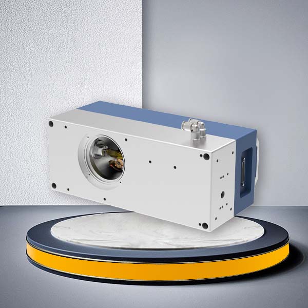
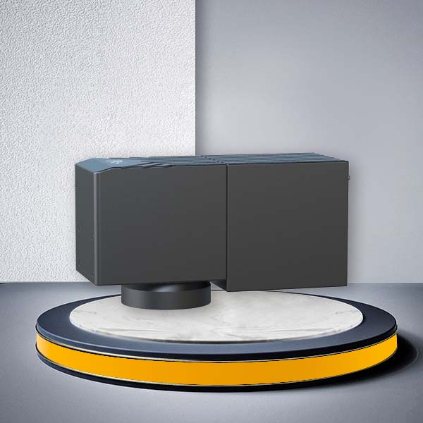
JCZ supplies the G3 Series 2D Galvo Scanner for industrial laser marking, engraving, cutting, cleaning and precision processing systems. Available in G3 Base, G3 STD and G3 ULT configurations, the series combines high-speed beam positioning, repeatable scanning accuracy and low thermal drift for different industrial processing requirements.
With a standard 10 mm input aperture, ±0.35 rad scan angle, XY2-100 interface and multiple wavelength options, G3 provides a flexible scanning platform for laser equipment manufacturers and system integrators. We also offer customized aperture sizes, optical coatings, mirror materials, communication interfaces, cooling configurations and mechanical structures to match specific OEM machine designs.
Whether you are developing a standard laser marking machine, a high-speed production system or precision processing equipment, JCZ can help you select and configure the appropriate G3 scanner.
G3 Series 2D Galvo Scanner Models
The G3 Series includes three configurations: G3 Base, G3 STD and G3 ULT. Each model has a different balance of scanning speed, dynamic response, linearity and long-term stability.
| Model | Product Positioning | Main Performance Advantage | Typical Application Direction |
|---|---|---|---|
| G3 Base | Standard Industrial Processing | Cost-effective performance for general laser processing | Standard marking, engraving, cutting and cleaning |
| G3 STD | High-Speed Industrial Processing | Higher marking and positioning speeds with fast response | High-speed marking, rapid QR code processing and production-line applications |
| G3 ULT | High-Precision Processing | Lower nonlinearity and improved long-term drift performance | Semiconductor processing, FPC cutting and precision applications |
G3 Base – Standard 2D Galvo Scanner
The G3 Base is designed for standard industrial laser processing applications requiring reliable beam positioning and consistent scanning performance.
With a marking speed of 5,000 mm/s, positioning speed of 10,000 mm/s and repeatability of less than 2 μrad, G3 Base provides a practical configuration for general laser marking, engraving, cutting and cleaning equipment.
It is suitable for OEM machine manufacturers seeking a balance between scanning performance, system configuration and equipment cost.
G3 STD – High-Speed 2D Galvo Scanner
The G3 STD is designed for applications requiring faster scanning and positioning performance.
Its marking speed reaches 10,000 mm/s, with a positioning speed of 16,000 mm/s. A tracking error of 0.11 ms and 1% full-scale response time of 0.26 ms support demanding dynamic scanning requirements.
The G3 STD is suitable for high-speed laser marking, rapid QR code processing, automated production equipment and applications involving frequent beam movement.
G3 ULT – High-Precision 2D Galvo Scanner
The G3 ULT is designed for applications where linearity, repeatability and long-term scanning stability are important selection criteria.
Compared with G3 Base and G3 STD, G3 ULT provides improved nonlinearity and 8-hour drift performance, with nonlinearity below 0.4% and drift below 0.1 mrad over 8 hours.
It is suitable for precision laser material processing, semiconductor processing, FPC cutting, flexible material cutting and other applications requiring consistent scanning accuracy.
G3 Base vs G3 STD vs G3 ULT: Technical Specifications
Use the following comparison to evaluate the three G3 configurations according to your processing speed, precision and stability requirements.
| Parameter | G3 Base | G3 STD | G3 ULT |
|---|---|---|---|
| Input Diameter | 10 mm | 10 mm | 10 mm |
| Tracking Error | 0.20 ms | 0.11 ms | 0.11 ms |
| Marking Speed | 5,000 mm/s | 10,000 mm/s | 8,000 mm/s |
| Positioning Speed | 10,000 mm/s | 16,000 mm/s | 15,000 mm/s |
| 1% Full Scale | 0.32 ms | 0.26 ms | 0.26 ms |
| 10% Full Scale | 1.20 ms | 0.62 ms | 0.62 ms |
| Repeatability | <2 μrad | <2 μrad | <2 μrad |
| Gain Drift | <150 ppm/K | <100 ppm/K | <100 ppm/K |
| Offset Drift | <50 μrad/K | <25 μrad/K | <25 μrad/K |
| Drift Over 8 Hours | <0.2 mrad | <0.15 mrad | <0.1 mrad |
| Nonlinearity | <1% | <1% | <0.4% |
| Scan Angle | ±0.35 rad | ±0.35 rad | ±0.35 rad |
| Interface | XY2-100 | XY2-100 | XY2-100 |
| Wavelength | 10600 / 1064 / 532 / 355 nm | 10600 / 1064 / 532 / 355 nm | 10600 / 1064 / 532 / 355 nm |
| Input Voltage | ±15 V DC | ±15 V DC | ±15 V DC |
| Rated Current | 3 A | 3 A | 5 A |
| Weight | 1,800 g | 1,800 g | 2,100 g |
| Working Temperature | 25 ±10°C | 25 ±10°C | 25 ±10°C |
All three models use a 10 mm standard input aperture and XY2-100 interface. The main differences are their dynamic response, scanning speed, thermal drift and linearity.
How to Choose the Right G3 Galvo Scanner
Selecting a galvo scanner should start with the actual processing requirements rather than the maximum speed listed in a specification sheet.
1. Choose According to Marking Speed
If your equipment requires frequent beam movement and short processing cycles, compare the marking speed, positioning speed and step response time together.
| Processing Requirement | Recommended Model | Selection Reason |
|---|---|---|
| General industrial marking | G3 Base | Balanced performance for standard processing |
| High-speed marking | G3 STD | Highest published marking speed in the G3 range |
| Rapid QR code processing | G3 STD | Fast positioning and dynamic response |
| Precision marking with stability requirements | G3 ULT | Improved nonlinearity and long-term drift |
The maximum marking speed does not directly represent actual production throughput. Processing results also depend on marking content, line spacing, laser parameters, material characteristics and optical configuration.
2. Choose According to Precision and Stability
For precision processing, evaluate repeatability, nonlinearity, gain drift and offset drift together.
| Performance Requirement | G3 Base | G3 STD | G3 ULT |
|---|---|---|---|
| Repeatability <2 μrad | Yes | Yes | Yes |
| Nonlinearity <1% | Yes | Yes | Yes |
| Nonlinearity <0.4% | — | — | Yes |
| Gain Drift <100 ppm/K | — | Yes | Yes |
| Offset Drift <25 μrad/K | — | Yes | Yes |
| 8-Hour Drift <0.1 mrad | — | — | Yes |
For applications where repeatability is the primary requirement, all three models provide a published value below 2 μrad. When lower nonlinearity and improved long-term stability are more important, G3 ULT is the preferred configuration.
3. Choose According to the Processing Application
| Application | Main Processing Requirement | Recommended G3 Configuration |
|---|---|---|
| General metal marking | Stable scanning and standard production performance | G3 Base / STD |
| Industrial engraving | Consistent beam positioning and processing accuracy | G3 Base / STD / ULT |
| High-speed QR code marking | Fast scanning and positioning | G3 STD |
| Semiconductor processing | Precision scanning and low drift | G3 ULT |
| FPC cutting | High linearity and stable beam positioning | G3 ULT |
| Flexible material cutting | Repeatable scanning and process consistency | G3 ULT |
| Laser cleaning | Appropriate scan speed and working-field configuration | G3 Base / STD |
| Laser cutting | Scanning dynamics and optical configuration matched to the process | G3 STD / ULT |
For dedicated high-power laser welding equipment, see our G3 Weld High Precision Welding Galvo Scanner.
For curved surfaces or workpieces with changing heights, evaluate the G3-3D Galvo Scanner, which adds Z-axis focus adjustment.
Dynamic Performance, Repeatability and Thermal Stability
The G3 Series provides several dynamic and precision parameters to help equipment designers evaluate scanning performance.
Dynamic Response and Scanning Speed
The marking speed and positioning speed determine different aspects of galvo movement.
- Marking Speed describes the speed of beam movement during processing.
- Positioning Speed describes the speed of movement between processing positions.
- Tracking Error evaluates the dynamic response of the scanning system.
- Step Response Time measures the response to a commanded change in position.
For high-speed applications, these parameters should be evaluated together with marking content, field size and laser processing conditions.
G3 STD provides the highest published marking speed and positioning speed in the current G3 range, making it suitable for applications with demanding scanning-cycle requirements.
Repeatability and Nonlinearity
Repeatability and nonlinearity describe different aspects of scanning accuracy.
Repeatability indicates the consistency of repeated positioning, while nonlinearity describes deviations from the expected linear scanning relationship.
The G3 Series provides repeatability below 2 μrad across all three configurations. G3 ULT further improves the published nonlinearity specification to below 0.4%.
For applications requiring more demanding precision targets, customized scanning configurations can be evaluated according to the required optical and mechanical design.
Thermal Drift and Long-Term Stability
Temperature changes can affect the positioning behavior of a galvanometer scanner during continuous operation.
The G3 Series provides gain drift, offset drift and 8-hour drift specifications for evaluating its thermal stability.
| Stability Parameter | G3 Base | G3 STD | G3 ULT |
|---|---|---|---|
| Gain Drift | <150 ppm/K | <100 ppm/K | <100 ppm/K |
| Offset Drift | <50 μrad/K | <25 μrad/K | <25 μrad/K |
| Drift Over 8 Hours | <0.2 mrad | <0.15 mrad | <0.1 mrad |
G3 ULT is the preferred option when lower long-term drift is a key requirement.
For customized projects, JCZ can also configure enhanced thermal management, cooling arrangements and performance targets according to the operating environment and application requirements.
Optical Configuration and Wavelength Compatibility
The optical configuration of a galvo scanner must match the laser source, beam diameter, mirror aperture and focusing lens.
The G3 Series supports four standard wavelength options, with additional optical configurations available for customized projects.
Laser Wavelength and Mirror Configuration
| Configuration Item | Standard Configuration | Custom Options |
|---|---|---|
| Laser Wavelength | 355 nm / 532 nm / 1064 nm / 10600 nm | 425–465 nm / 513–534 nm and other specified wavelength configurations |
| Mirror Substrate | Model-specific optical configuration | Silicon / Fused Silica / Silicon Carbide |
| Mirror Coating | Wavelength-matched coating | High-reflectivity / Broadband / Multi-wavelength / Short-pulse / Polarization-maintaining coatings |
| Mirror Configuration | Standard optical assembly | Customized mirror size, material and coating |
| Optical Alignment | Standard optical configuration | Application-specific optical alignment |
The mirror substrate and coating should be selected according to wavelength, laser power density, pulse characteristics and scanning requirements.
For example, a 355 nm UV system requires optical components designed for UV transmission and reflection, while a 1064 nm fiber laser system needs a compatible infrared optical configuration.
JCZ can configure optical components according to the selected laser source and processing requirements.
View the JCZ Laser Source Range to compare compatible laser technologies.
Input Aperture and Beam Compatibility
The standard G3 configuration uses a 10 mm input aperture. Customized scanner configurations can be supplied with different aperture sizes to accommodate different beam diameters and optical designs.
| Configuration | Available Aperture |
|---|---|
| Standard G3 Series | 10 mm |
| Custom Aperture Options | 7 mm / 8.5 mm / 12 mm / 14 mm / 15 mm / 20 mm / 30 mm |
When selecting an aperture, consider:
- Laser beam diameter at the scanner entrance.
- Beam quality and beam expansion configuration.
- Mirror clear aperture.
- Laser wavelength and mirror coating.
- Required scan angle and optical field.
- Compatibility with the selected F-theta lens.
A larger aperture does not automatically produce a larger marking field. The final working field also depends on the optical design and focusing lens.
Scan Angle and Optical Design
The standard G3 Series provides a scan angle of ±0.35 rad.
Customized scan-angle configurations can be developed according to the required optical geometry, including options up to ±0.393 rad.
For OEM equipment, scan angle should be evaluated together with focal length, working distance, beam diameter and required processing field.
Mirror Displacement and Optical Customization
For projects requiring specific optical-axis positioning or mechanical integration, JCZ can customize:
- Beam displacement.
- Optical-axis height.
- Mirror dimensions.
- Mirror substrate and coating.
- Scanner housing.
- Optical entrance and exit arrangements.
- Mounting and alignment structures.
Provide the existing optical drawing or machine layout so the scanner configuration can be evaluated against the complete beam path.
F-theta Lens Matching and Working Field Selection
The galvo scanner and F-theta lens form an integrated optical system. Selecting a scanner without considering the lens may result in an unsuitable beam diameter, working distance, scan field or spot size.
JCZ provides both flat-field and telecentric F-theta lens configurations for different industrial laser processing requirements.
| Lens Configuration | Main Characteristics | Application Direction |
|---|---|---|
| Flat-Field F-theta Lens | Conventional flat-field focusing for industrial scanning applications | Standard marking, engraving and scanning |
| Telecentric F-theta Lens | Controls the beam incidence angle to keep the output beam nearly perpendicular to the working plane | Precision processing requiring telecentric beam delivery |
JCZ’s flat-field F-theta lens range covers UV to IR wavelength configurations, with focal lengths from 63 mm to 1450 mm.
View the available options:
Information Required for Lens Matching
| Selection Parameter | Information to Confirm |
|---|---|
| Laser Wavelength | 355 / 532 / 1064 / 10600 nm or customized wavelength |
| Scanner Aperture | 10 mm standard or customized aperture |
| Input Beam Diameter | Actual beam diameter at the scanner entrance |
| Focal Length | Required focal length |
| Working Distance | Distance between the lens and workpiece |
| Scan Field | Required marking or processing area |
| Spot Size | Required focused spot diameter |
| Laser Power | Average power, peak power and pulse characteristics where applicable |
For example, a larger scan field generally requires a different focal length and optical design. The resulting spot size and working distance must also be considered.
Send your optical parameters to JCZ for a matched scanner and lens configuration rather than selecting the lens by focal length alone.
Electrical Interface and Controller Compatibility
The G3 Series uses the XY2-100 interface as its standard communication configuration.
For customized equipment, alternative communication and control configurations are also available according to the selected scanner and controller architecture.
| Parameter | Standard Configuration | Custom Options |
|---|---|---|
| Communication Interface | XY2-100 | SL2-100 / ST2-100 / NVL-100 / XY2-100 Enhanced |
| Control Resolution | According to standard configuration | 16-bit / 20-bit |
| Input Voltage | ±15 V DC | Customized electrical configuration |
| Rated Current | Base / STD: 3 A; ULT: 5 A | According to selected scanner and drive configuration |
| Electrical Connection | Standard scanner connection | Customized connector and pin configuration |
Matching the Galvo Scanner with a Laser Controller
A compatible controller is essential for coordinating the laser source, scanner movement, processing data and external machine signals.
For EZCAD3-based systems, the DLC2-V4 Laser Controller supports mainstream laser types and galvo control protocols, including XY2-100 and other supported interfaces.
For compatible EZCAD2-based systems, the LMCPCIE Laser Controller provides PCIe-based laser and digital galvo control.
For large-format continuous laser processing requiring coordination between the galvanometer and motion platform, the ZEUS Intelligent-Continuous Laser Processing Controller is another system-level option.
Before ordering, confirm the following:
- Galvo scanner model and communication protocol.
- Controller model and firmware configuration.
- Laser source interface and control requirements.
- Required motion axes and encoder feedback.
- Electrical connections and I/O requirements.
- Software and calibration configuration.
The controller should be selected according to the complete machine architecture, not solely according to the scanner interface.
Mechanical Design, Cooling and Environmental Customization
For OEM equipment manufacturers, mechanical compatibility is as important as optical performance.
The standard G3 models have different weights and electrical requirements. Additional mechanical and thermal configurations can be customized for machine integration.
| Parameter | Standard G3 Configuration | Custom Options |
|---|---|---|
| Scanner Weight | Base: 1,800 g / STD: 1,800 g / ULT: 2,100 g | According to aperture and housing design |
| Housing Dimensions | Model-specific standard structure | Customized scanner dimensions |
| Mounting Structure | Standard product configuration | Customized mounting holes and mechanical interfaces |
| Connector Position | Standard configuration | Customized connector position and orientation |
| Cooling Method | Standard product configuration | Air Cooling / Water Cooling / Water Temperature Control |
| Air Flushing | Project-dependent | Optional Air Flushing |
| Working Temperature | 25 ±10°C | Extended operating range of 0–45°C |
Customized mechanical configurations can include:
- Scanner housing dimensions.
- Mounting hole positions.
- Optical entrance and exit positions.
- Connector direction.
- Beam displacement.
- Cooling connections.
- Cable routing and installation space.
For projects requiring water cooling or air flushing, the cooling arrangement should be defined together with the mirror configuration, laser power and operating environment.
Provide a mechanical drawing or available installation space when requesting an OEM configuration.
G3 Series Applications and Model Selection
The G3 Series can be configured for different industrial laser processing requirements. The correct model depends on processing speed, positioning accuracy, optical configuration and the workpiece characteristics.
Industrial Laser Marking and Engraving
G3 Base, G3 STD and G3 ULT can be evaluated for industrial laser marking and engraving systems.
| Requirement | Recommended Configuration |
|---|---|
| Standard metal marking | G3 Base |
| High-speed marking | G3 STD |
| Repeated precision marking | G3 ULT |
| QR code and variable-data marking | G3 STD |
| Customized wavelength or aperture | Custom G3 configuration |
For systems using a fiber laser, UV laser or CO2 laser, confirm the wavelength and optical coating before selecting the scanner.
Semiconductor and FPC Processing
G3 ULT is suitable for evaluating precision processing applications that require improved linearity, repeatability and long-term stability.
Potential application directions include:
- Semiconductor material processing.
- FPC cutting.
- Flexible material cutting.
- Precision laser marking.
- Biomedical testing-related laser processing.
The final configuration should be selected according to the required processing accuracy, material, spot size, scan field and production conditions.
Laser Cutting and Cleaning
G3 Base and G3 STD can be considered for laser cutting and cleaning equipment where the required scanning performance matches the application.
| Processing Requirement | Selection Consideration |
|---|---|
| Standard cutting applications | Scan field, optical power density and positioning performance |
| High-speed scanning | Marking/processing speed and dynamic response |
| Surface cleaning | Scan pattern, processing width and laser parameters |
| Precision material removal | Repeatability, linearity and focused spot size |
For high-power welding equipment, see the dedicated G3 Weld Galvo Scanner, which is designed specifically for laser welding systems.
Other G3 Configurations for Different Processing Requirements
JCZ also supplies other galvo scanner series for projects with different optical architectures.
| Product | Main Function | When to Consider |
|---|---|---|
| GO7 Series 2D Galvo Scanner | General-purpose 2D scanning | Standard 2D laser marking systems |
| G3 Series 2D Galvo Scanner | Industrial 2D scanning with Base, STD and ULT configurations | Higher requirements for dynamic response, precision and stability |
| G3-3D Galvo Scanner | 3D scanning with Z-axis focus adjustment | Curved, stepped and height-varying workpieces |
| GO3D-T Series | 3D dynamic-focus scanning | Projects requiring multiple aperture and dynamic-focus configurations |
| G3 Weld Galvo Scanner | Dedicated welding galvo scanner | High-power laser welding systems |
This product separation helps equipment manufacturers select a scanner according to the actual processing architecture rather than comparing products with different functions as if they were interchangeable.
G3 Series Customization Options for OEM Projects
JCZ provides customized G3 configurations for laser equipment manufacturers, system integrators and industrial automation projects.
Customization can cover optical, mechanical, electrical and performance requirements.
| Customization Category | Available Options |
|---|---|
| Scanner Aperture | 7 / 8.5 / 10 / 12 / 14 / 15 / 20 / 30 mm |
| Laser Wavelength | 355 / 532 / 1064 / 10600 nm and additional specified wavelength bands |
| Mirror Substrate | Silicon / Fused Silica / Silicon Carbide |
| Mirror Coating | High-reflectivity / Broadband / Multi-wavelength / Short-pulse / Polarization-maintaining |
| Scan Angle | Standard ±0.35 rad; customized configurations up to ±0.393 rad |
| Marking Speed | Customized performance configurations up to 12,000 mm/s |
| Positioning Speed | Customized performance configurations up to 21,000 mm/s |
| Tracking Error | Customized targets from 0.10–0.14 ms |
| Repeatability | Customized high-precision configurations below 1 μrad |
| Nonlinearity | Customized configurations down to ≤0.1% |
| Gain Drift | Customized configurations from <8–50 ppm/K |
| Offset Drift | Customized configurations from <10–20 μrad/K |
| Long-Term Drift | Customized configurations from <0.05–0.10 mrad over 8 hours |
| Communication Interface | XY2-100 / SL2-100 / ST2-100 / NVL-100 / XY2-100 Enhanced |
| Control Resolution | 16-bit / 20-bit |
| Mirror and Optical Assembly | Customized mirror dimensions, beam displacement and optical alignment |
| Mechanical Structure | Customized housing, mounting holes and connector positions |
| Cooling | Air Cooling / Water Cooling / Water Temperature Control / Air Flushing |
| Electrical Configuration | Customized voltage, current and connector arrangements |
Customized performance values depend on the selected aperture, mirror dimensions, wavelength, scan angle, drive configuration and test conditions. Multiple maximum performance targets should be evaluated as one complete configuration rather than assumed to apply simultaneously to every scanner.
OEM Configuration Process
| Step | Information or Requirement | JCZ Configuration Focus |
|---|---|---|
| 1. Application Review | Processing material, process type and production requirements | Identify the appropriate G3 model |
| 2. Optical Review | Wavelength, beam diameter, aperture and lens | Match mirrors, coatings and optical components |
| 3. Performance Review | Speed, repeatability, linearity and thermal stability | Select standard or customized performance |
| 4. Mechanical Review | Installation space, mounting and connector positions | Configure the scanner structure |
| 5. Electrical Review | Controller, protocol, power and wiring | Confirm system compatibility |
| 6. Quotation | Model, configuration and required quantity | Prepare the corresponding product quotation |
Technical Information Required for a G3 Galvo Scanner Quotation
To select the correct G3 configuration, please provide the following information when requesting a quotation.
| Information | Details to Provide | Why It Matters |
|---|---|---|
| Application | Marking / Engraving / Cutting / Cleaning / Other | Determines performance requirements |
| Laser Type | Fiber / UV / Green / CO2 / Other | Determines wavelength and optical configuration |
| Laser Model | Manufacturer and model number | Confirms laser compatibility |
| Laser Wavelength | 355 / 532 / 1064 / 10600 nm or other | Determines mirror coating |
| Laser Power | Average power and peak power where applicable | Helps evaluate mirror and coating requirements |
| Input Beam Diameter | Beam diameter at the scanner entrance | Determines aperture selection |
| Processing Field | Required working area | Determines lens and scan-angle configuration |
| Focal Length | Required F-theta lens focal length | Helps match the optical system |
| Working Distance | Distance from lens to workpiece | Determines lens selection |
| Speed Requirement | Required marking and positioning speed | Determines Base, STD, ULT or custom configuration |
| Precision Requirement | Repeatability, linearity and drift targets | Determines performance configuration |
| Controller | Existing controller model | Confirms communication compatibility |
| Interface | XY2-100 or other required protocol | Determines electrical configuration |
| Mechanical Requirements | Dimensions, mounting and connector position | Supports OEM installation |
| Cooling | Air cooling / Water cooling / Other | Determines thermal configuration |
| Quantity | Required order quantity | Supports quotation preparation |
If you already have an existing scanner, controller or optical drawing, send the product label, wiring diagram or mechanical drawing together with your inquiry. This helps reduce configuration uncertainty during the selection process.
Frequently Asked Questions About G3 Series 2D Galvo Scanners
1. What is the difference between G3 Base, G3 STD and G3 ULT?
The three models differ mainly in marking speed, positioning speed, dynamic response, nonlinearity and long-term thermal drift.
G3 Base is designed for standard industrial processing, G3 STD provides higher marking and positioning speeds, and G3 ULT offers improved linearity and long-term stability for precision applications.
2. Which G3 model has the highest marking speed?
G3 STD has the highest published marking speed in the standard G3 range at 10,000 mm/s, with a positioning speed of 16,000 mm/s.
For projects requiring higher customized speed targets, JCZ can evaluate configurations up to 12,000 mm/s marking speed and 21,000 mm/s positioning speed.
3. Is the G3 Series available with apertures other than 10 mm?
Yes. The standard G3 models use a 10 mm input aperture. Customized configurations are available with 7 mm, 8.5 mm, 12 mm, 14 mm, 15 mm, 20 mm and 30 mm apertures.
The appropriate aperture should be selected according to the input beam diameter, mirror configuration and optical design.
4. Which laser wavelengths are supported by G3?
The standard G3 Series supports 355 nm, 532 nm, 1064 nm and 10600 nm configurations.
Additional wavelength configurations can also be customized. Mirror substrate and coating selection should match the laser wavelength and power requirements.
5. Does G3 support the XY2-100 communication protocol?
Yes. XY2-100 is the standard interface for G3 Base, STD and ULT.
Customized communication configurations, including SL2-100, ST2-100, NVL-100 and XY2-100 Enhanced, are also available. Confirm the controller model and protocol before ordering.
6. Which G3 model is suitable for semiconductor and FPC processing?
G3 ULT is the preferred starting point for these applications because it provides nonlinearity below 0.4%, repeatability below 2 μrad and 8-hour drift below 0.1 mrad.
The final selection should also consider the laser wavelength, spot size, processing field and required material-removal accuracy.
7. Does the G3 Series include a laser controller?
The G3 is a galvo scanner head. The laser controller, laser source, software and other machine components are selected according to the complete system architecture.
JCZ provides compatible laser control options, including the DLC2-V4 Controller and LMCPCIE Controller.
8. Can G3 be used for laser welding?
G3 can be evaluated for laser processing applications where its scanning performance and optical configuration meet the requirements. For dedicated high-power welding systems, JCZ also provides the G3 Weld Galvo Scanner, which has a dedicated welding configuration.
9. Can G3 process curved or height-varying workpieces?
The standard G3 Series is a 2D galvo scanner designed for XY-plane scanning. For applications requiring active Z-axis focus adjustment on curved, stepped or height-varying surfaces, consider the G3-3D Galvo Scanner.
Request a G3 Series 2D Galvo Scanner Configuration and Quote
Choosing a suitable galvo scanner requires more than comparing marking speeds. Aperture, wavelength, mirror coating, scan angle, F-theta lens, controller protocol, mechanical installation and thermal requirements all affect the final system configuration.
JCZ provides G3 Base, G3 STD and G3 ULT configurations, together with customized optical, mechanical, electrical and performance options for industrial laser equipment manufacturers and system integrators.
Send us your laser source model, wavelength, input beam diameter, required processing field, controller information and application requirements.
Our team can evaluate the appropriate G3 model, recommend the optical and electrical configuration, and prepare a quotation based on your project requirements.
Contact JCZ today to discuss your G3 Series 2D Galvo Scanner requirements and request a customized configuration.