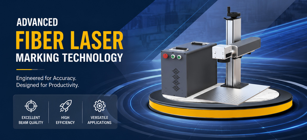
Tips for Maintaining a Portable Fiber Laser Marking Machine
Portable fiber laser marking machines earn their keep in workshops where mobility matters. They mark serial numbers on assembly lines, engrave logos on curved surfaces, and etch QR codes in field-service settings. One thing all operators learn fast: a unit that travels gets bumped, dusty, and pushed to thermal limits. Ignoring that abuse doesn’t just risk sloppy marks. It shortens the life of a precision tool that often costs five figures.
Maintenance looks boring on a checklist, but it is the single biggest lever you can pull to protect that investment. This guide lays out the routines, the numbers, and the easy-to-miss details that keep a portable fiber laser running predictably. You’ll find specifics on optics care, galvo alignment, fiber integrity, cooling, and software diagnostics. JCZ has spent over twenty years developing the control systems behind machines exactly like these. Their Laser Software family—including the widely used Ezcad2 Software and its next‑generation sibling, Ezcad3 Software—gives operators a dashboard to spot drift early, before a job gets scrapped. You will see those tools mentioned where they matter most.
The Lens and Protective Window: Where Power Is Lost First
A fiber laser’s output window faces the work zone directly. Fume, spatter, and airborne dust collect there. Even a thin film cuts transmission efficiency. Independent studies by the Laser Institute of America indicate that surface contamination accounts for over 60% of service calls on industrial laser systems. In portable use, that number climbs because the unit often operates without the enclosed cabin that would shield stationary equipment.
You can measure the loss yourself. A unit that delivered 30 W at the focal point yesterday might only put out 22 W today—a 25–30 % drop that translates into faded marks and longer cycle times. ISO 11146-1, which defines beam quality measurement, assumes clean optics as a baseline. If you are far from that baseline, your M² value drifts, and so does mark consistency.
Cleaning takes ten minutes. You need lint‑free swabs, reagent‑grade isopropyl alcohol (or a manufacturer‑recommended solvent), and compressed air filtered to 0.3 µm. Avoid canned dusters that spit propellant. One puff of liquid gas onto a warm lens thermally shocks the coating and can create micro‑cracks. A quick sequence: blow loose particles, moisten a swab, wipe once from center to edge, discard the swab, repeat with a fresh one. No circular scrubbing. That just re‑deposits debris in the optical center.
A common mistake is ignoring the back side of the protective window. Operators wipe the front, but vapor can sneak around seals and condense on the inside. If your portable unit has a removable window cartridge, pull it out and inspect both surfaces under a bright light every 40–50 operating hours.
If you notice that even a clean lens cannot restore expected power, the problem may sit deeper. The Ezcad2 Software laser‑control platform includes a power‑mapping utility. Run it weekly on a calibrated meter. Record the values. When you see a steady decline across multiple power levels, you have a data trail that points to pump diode aging rather than dirty optics. That saves you from disassembling the head needlessly.
Galvo Scanner and Beam Alignment: The Half‑Millimeter Problem
The galvo mirrors that steer the beam in a portable fiber laser sit inside a sealed compartment. Still, vibration and temperature swings loosen set screws slowly. A drift of only half a millimeter at the focal plane turns a crisp 0.1 mm line into a blurred 0.15 mm ghost. For QR codes or 2D matrix symbols, that mismatch can push verifier grades from “A” to “D” per ISO/IEC 15415.
You can catch this drift before it ruins a batch. Place a piece of black anodized aluminum on the marking table. Load a simple grid pattern in your control software. Mark it at three points—center, near the upper‑left corner, and near the lower‑right—and measure the actual coordinates with a caliper. The deviation between commanded coordinates and real positions tells you the angular error. Most galvo systems can be corrected digitally via the correction file.
The Ezcad3 Software architecture has a dedicated 3D correction table that compensates for off‑axis distortion, a feature particularly useful on machines that do deep engraving. If your portable unit includes a Z‑axis dynamic focus module, the software blends the galvo and focus corrections into one calibration routine. Run it after air freight, after a fall from a cart, or any time the ambient temperature shifts more than 5 °C since the last calibration.
Physically, open the scanner housing only in a clean environment. Dust on the mirrors scatters the beam, reducing peak power density. A 0.5 µm particle can absorb enough energy to pit the coating. When you do need to clean a mirror, use the same drop‑and‑drag technique you use on lenses, but be even more delicate. The mirror surfaces are typically silicon or fused silica with an HR coating that tolerates only mild pressure.
A typical galvo scanner, such as those integrated into JCZ’s laser control ecosystem, operates at scan speeds up to 15 m/s. At those velocities, even a tiny imbalance in the rotor can cause long‑term bearing wear. Listen for high‑pitched chirps or rattles during a full‑field test pattern. If you hear them, the scanner needs factory rebalance. This is not a field repair.
Fiber Cable and Connectors: Bends That Bleed Light
Portable use strains the fiber delivery cable more than rack‑mounted systems. The cable gets coiled, uncoiled, stepped on, and pinched. Inside, a doped silica core guides the laser light by total internal reflection. Tight bends force the light into the cladding, heating the jacket and triggering a thermal failure that rolls out over weeks.
Every fiber has a minimum bend radius specified by its manufacturer. For the typical 20 W–50 W air‑cooled cable found on portable markers, that radius is usually in the range of 200 mm for long‑term static routing and 100 mm for momentary handling. Exceed those numbers and microscopic stress fractures form at the core‑cladding interface. You will not see them. You will see a slow power loss at the output—maybe 3 % per month—until the cable fails entirely.
Check connectors at both ends monthly. The QCS connector on the laser head and the isolator input port are critical. Even a 5 µm dust particle on the fiber tip can absorb 20 W of energy and burn a permanent spot. Blow the connector with oil‑free compressed air before mating. Never touch the ferrule with bare fingers. A fingerprint contains acids that etch the glass over days.
Industry best practices, drawn from the ANSI Z136 laser safety standard and field reports by the Laser Institute of America, recommend an annual connector‑face inspection with a fiberscope for systems in heavy mobile use. If you cannot afford a fiberscope, at least measure the back‑reflection using a power meter and a beam splitter. A jump from the typical 0.5 % return to 2 % indicates a dirty or damaged face. That is the point where a simple clean can prevent a $800 cable replacement.
Cooling and Airflow: The 10-Degree Rule
Most portable fiber laser markers are air‑cooled. They rely on a small fan and a heatsink to keep the pump diodes below their maximum junction temperature—often around 50 °C. Once the diode package exceeds that, every subsequent 10 °C rise shortens its expected lifetime by half, a relationship known as the Arrhenius Rule applied to semiconductor reliability.
A fan clogged with lint cuts airflow by 40 % or more. Check the intake and exhaust grilles weekly. Use a soft brush or a vacuum, not compressed air, to avoid blowing debris deeper inside. If the unit has a removable filter mesh, wash it in warm water with mild soap, dry it completely, and reinstall it. Record the cleaning date. You will start noticing patterns—perhaps a shop with heavy cardboard dust plugs filters in three weeks rather than the standard six.
Environmental conditions matter as much as internal cleanliness. Fiber lasers operate reliably from roughly 15 °C to 35 °C ambient, but condensation risk kicks in when the laser head temperature drops below the dew point. If you move the unit from a cold truck into a warm, humid factory, let it acclimatize for 30 minutes before powering on. Place a small humidity indicator card inside the accessory case. A reading above 60 % RH demands caution. Condensation on the electronic drivers or the fiber connector can cause a short or an immediate optical damage event.
Water‑cooled portable units exist, though they are less common. They add a pump, reservoir, and heat exchanger. Check coolant conductivity every 250 hours. Deionized water alone works, but commercial coolants with anti‑algal and anti‑corrosion packages maintain stability longer. Typical conductivity should stay below 5 µS/cm. Above 20 µS/cm, replace the coolant and flush the loop. The same software suite that drives your marking—whether the basic Ezcad2 Software or the multi‑head Ezcad3 Software—can often display diode temperature via the laser‑source communication protocol. Set an alarm threshold 5 °C below the maximum. That gives you a cushion to shut down gracefully.
Software and Calibration: Data That Prevents Downtime
Hardware maintenance feels tangible. Software maintenance seems invisible, but it is where you catch problems at their very beginning. The control software logs power-on hours, galvo cycles, and internal error codes. Few operators look at those logs until something breaks.
If you use Laser Software from JCZ, open the diagnostics panel once a month. Look for driver overcurrent events, communication timeouts, or repeated retries on the laser enable signal. One overcurrent event in a month may be a fluke. Three in a week suggests a deteriorating pump diode or a failing galvo driver. You can order a replacement board while the unit still runs, rather than scrambling after a hard failure.
Firmware updates for the controller board and the laser source are not just about new features. They often contain revised temperature compensation coefficients or galvo calibration algorithms that extend hardware life. Keep a dedicated maintenance laptop with a known‑good version of the software. Before updating, back up your correction file and the system configuration. A botched firmware load can brick a controller. The typical recovery procedure—a CF card flash or a bootloader sequence—takes an engineer roughly two hours if you have the files. Without them, it turns into a round‑trip shipment.
Calibration extends beyond the galvo alignment mentioned earlier. The encoder feedback from a galvo scanner drifts slightly over millions of cycles. The software distortion‑correction table needs a refresh. Using a calibrated grid target (available from metrology suppliers for a few hundred dollars), you can quantify this drift. The specification for a new system is usually ±0.01 mm accuracy over a 110 mm x 110 mm field. After 500 million cycles, it might widen to ±0.03 mm. That is still acceptable for most deep engraving, but for fine electronics marking, a recalibration trims it back. Some Ezcad3 Software installations offer an automatic correction routine using a machine‑vision system, reducing the manual labor to a single click.
A quick overview of maintenance tasks and their recommended intervals helps you build a repeatable routine.
| Maintenance Task | Typical Interval | Key Measurement / Indicator | |—|—|—| | Lens / window cleaning | 40–50 operating hours (or visible haze) | Power drop >5% from baseline at nominal current | | Fiber connector inspection | Monthly (mobile); quarterly (stationary) | Back‑reflection >2% | | Air filter cleaning | Weekly | Airflow velocity drop (visual check) | | Galvo correction refresh | Every 1 000 hours or after mechanical shock | Field accuracy beyond ±0.03 mm | | Diode temperature trend | Monthly review of software logs | Steady rise of 3 °C over baseline | | Full system calibration | Annually (or 2 000 hours) | Marking quality on ISO/IEC 15415 verification |
These intervals are not carved in stone. A unit running 16 hours a day cutting bearing codes in a die‑casting plant will need lens cleaning every shift. A unit used lightly inside a laboratory might stretch to 200 hours. Let your data drive the schedule, not the calendar.
Pro Tips That Extend Machine Life Past the Warranty
Some tricks come only from time spent with the hardware. One: label the fiber cable with colored tape at the maximum safe bend radius point. When a new operator coils the cable, the tape serves as a visual stop. Two: after cleaning the lens, always run a short pulse burst on a graphite block or a piece of ceramic. This thermal cycles the coating gently and reveals any residual solvent smears before they burn into a permanent stain. Three: keep a log, not just in software but in a physical notebook. Record cleaning dates, power readings, and anything unusual—a hum, a smell, a mark shape that looked different. That log solves mysteries six months later when a failure pattern emerges. Four: when you are troubleshooting a mark quality issue, swap the fiber at an early stage. Even if you think it is fine, the mere act of swapping and testing the spare eliminates one major variable. Shops that wait until all else fails often discover the fiber was the culprit, wasting two days of diagnostics.
Frequently Asked Questions
How often should I clean the laser lens on a portable fiber marker? Most shops begin with a 40‑hour interval and adjust from there. Measure output power with a calibrated meter before and after cleaning; if you never see more than a 3 % drop, stretch the interval to 80 hours. In dirty environments, you may need to clean daily.
What causes sudden power loss in a fiber laser? Three culprits dominate: a contaminated optical surface, a damaged fiber connector, or a pump diode reaching end of life. Use the laser software’s power log to isolate whether the decline was gradual (optics or diode wear) or sudden (a connector burn or a fiber break).
Can I use compressed air from the shop line to dust off optics? Not recommended unless the line has a dedicated filter‑dryer that achieves a 0.01 µm particle removal and a dew point below −40 °C. Ordinary shop air contains oil mist and water that will cement debris to the lens.
Why does my machine lose accuracy after transport? The galvo mount can shift slightly. Even a 0.02 mm lateral displacement of a mirror changes the optical path enough to distort the marking field. Always run a quick positional test pattern after moving the unit.
Keeping the Machine Honest
Portable fiber laser markers are not maintenance‑free appliances. They are precision instruments that demand weekly attention—five minutes of cleaning, two minutes of listening, one minute of logging. The payoff is not subtle. It is the difference between a machine that runs eight years with a single diode swap and one that gets scrapped at year three.
Apply these tips in order of impact: protect the optics first, then the fiber, then keep the thermal baseline steady. Use the data your control software already collects. JCZ’s Laser Software gives you the window into the systems that matter most—galvo health, power trends, error logs. The Ezcad2 Software keeps things straightforward for daily marking tasks, while the Ezcad3 Software adds the precision and diagnostics that high‑end shops rely on. Grab the cleaning kit, open the log, and put today’s readings down. That simple habit turns maintenance from a reactive headache into a predictable, low‑cost routine.

OFFICIAL DRIVER UPDATE NOTICE

Top Factors That Affect Marking Quality in Handheld Fiber Laser Systems

Meet JCZ at Laser World of Photonics India 2026 in Bengaluru

Laser Marking Fabric with Portable Laser Engraver: Advanced UV Laser Marking Solutions for Modern Manufacturing

Laser Machine for Marking: The Ultimate Guide to Portable Fiber Engravers & MOPA Color Laser Marking

Laser Cleaning Machine for Wood: The Ultimate Guide to Safe, Precise & Eco-Friendly Wood Surface Cleaning