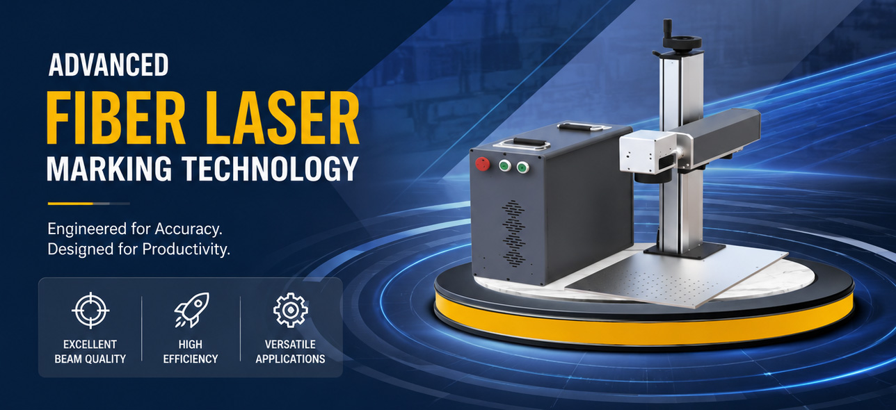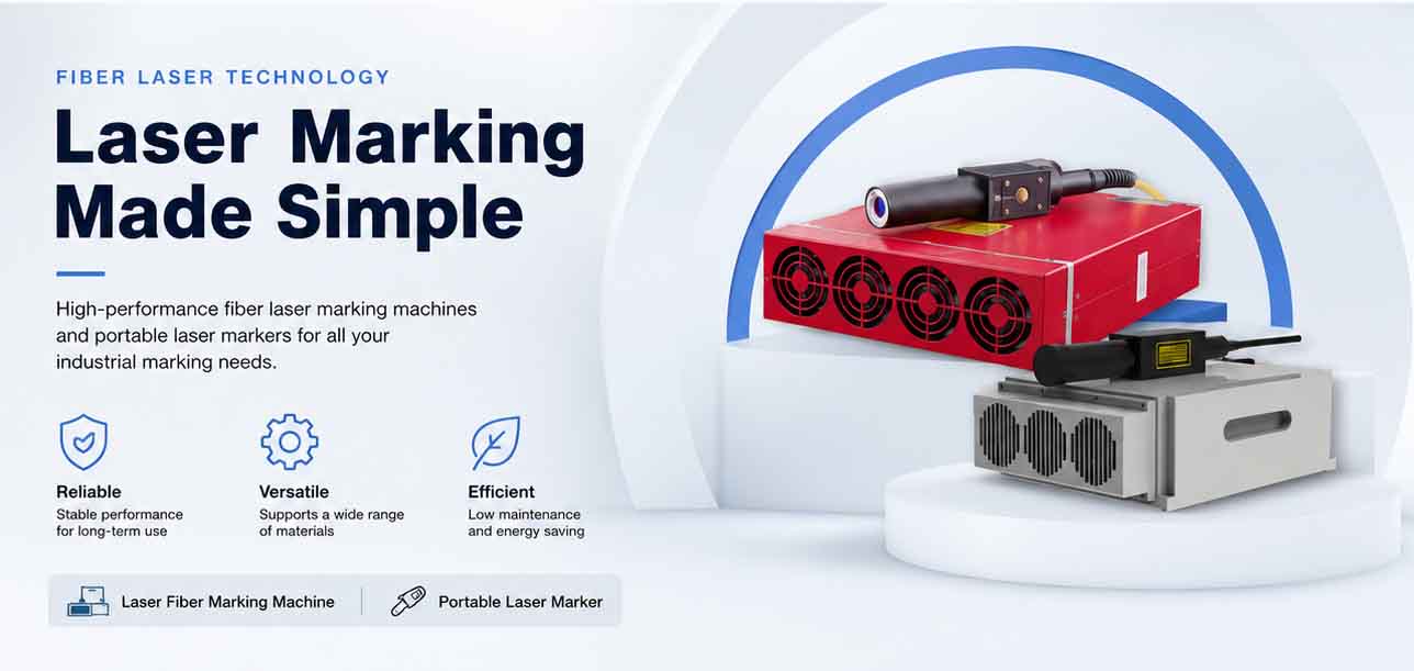
Review Checklist for Portable Fiber Laser Marker Samples
You just received a sample from a supplier and need to decide whether the portable fiber laser marker holds up under real production demands. The difference between a frictionless integration and a downtime magnet often comes down to how methodically you verify the machine before signing off. This checklist breaks that process into six hard-edged evaluation zones, giving you a repeatable way to compare metal engraving depth, software responsiveness, beam quality, and long-term serviceability — without getting lost in spec-sheet marketing.
The core of any checks worth doing ties back to the control software and the laser source. Whether you are running a PF‑2D system or integrating a compact all‑in‑one nanosecond laser, the same evaluation principles apply. We tap into years of working with Laser Software and field‑tested laser configurations to give you a framework that surfaces real capabilities, not just datasheet figures.
Quick Verdict
| Aspect | Assessment | |——–|————| | Recommended | Yes — provided software is Ezcad2/Ezcad3 and optical train passes the spot test | | Best for | Precision metal engraving on steel, aluminum, brass, and anodized layers in job‑shop or plant‑floor environments | | Biggest strength | Full control over waveform and vector parameters through a single software environment | | Key limitation | Portability can compromise beam stability if the galvanometer mounting is not thermally compensated |
What Is a Portable Fiber Laser Marker?
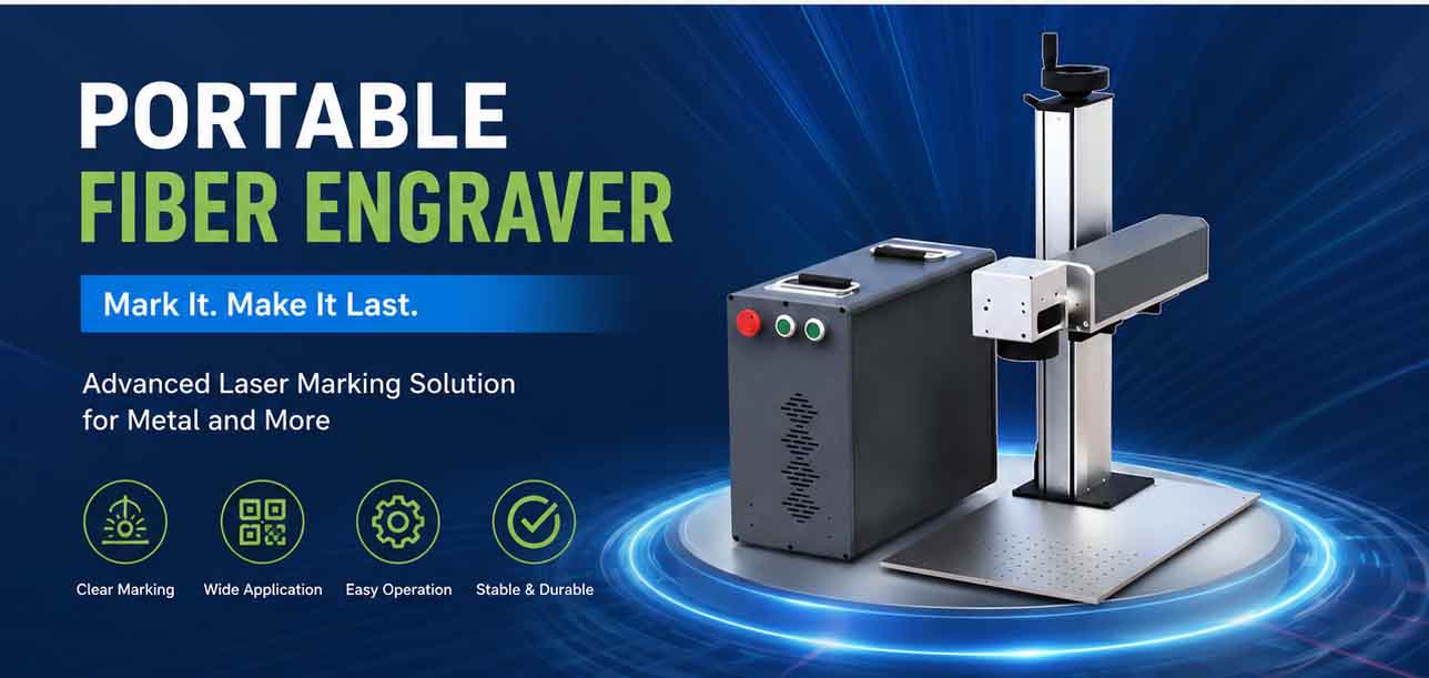
A portable fiber laser marker is a compact Q‑switched or MOPA fiber laser system integrated with a 2D galvanometer scan head, typically mounted on a lightweight gantry or handheld fixture. Its primary use case is direct part marking of metals, engineered plastics, and coated surfaces — serial numbers, barcodes, QR codes, logos, and deep engravings. The system is designed for machine builders, tier‑1 automotive suppliers, medical device manufacturers, and metal fabrication shops that need to mark large or immovable workpieces without repositioning them.
It does not replace a flood‑cooled, high‑duty‑cycle 100‑W laser cutting gantry; its scope is limited to engraving and superficial structuring. The critical differentiator among competing units almost always traces back to how the galvanometer and software communicate: a locked‑in controller‑galvo loop yields crisp 3‑µm repeatability, while an open‑loop budget system drifts within minutes of warm‑up.
Core Feature Analysis: The Six‑Point Review Checklist
1. Software Environment — Verdict: Strong
Before you even fire the laser, spend an hour with the control interface. If the software cannot import standard vector formats like DXF, AI, and SVG, or lacks field‑correction of distortion, you are already accepting compromise. A robust package should let you adjust pen parameters per object, configure variable‑speed filling, and preview the marking path in real time. Ezcad2 Software handles all those pain points with a dual‑axis splicing function and a flying‑mark interface that synchronizes with encoder input — critical when marking on a moving conveyor or large cylindrical parts. For high‑resolution tasks such as micro‑text inside medical implants, Ezcad3 Software uses a completely re‑written 64‑bit architecture that cuts data processing latency noticeably, a feature you will feel the moment you load a dense 2‑MB engraving file.
Use case: You are evaluating a sample plate that contains 14‑point QR codes, hairline logos, and deep‑fill recessed characters. The software must let you isolate each layer, assign a unique hatch interval, and vary power as the galvo slows at turn‑points. Without this level of control, you will either burn crisp corners or leave shallow centers — both of which translate to scrap parts in production.
Limitation: Ezcad2 operates in a 32‑bit environment and may become less responsive when handling multi‑layer engravings with more than 20 objects; Ezcad3 addresses this but requires a corresponding control board that supports USB 3.0 protocol.
2. Laser Source Characteristics — Verdict: Strong
Pull up the laser configuration file or technical datasheet and verify beam quality and temporal pulse shape. The Elite Series nanosecond lasers frequently integrated with JCZ control systems deliver an M² value below 1.2 across IR wavelengths (1064 nm), a number that directly impacts the smallest achievable spot size. A measured M² on a test report that surpasses 1.5 will degrade bare‑metal contrast and force you to over‑power the pulse just to compensate for a larger spot.
Check the pulse repetition rate range. The Elite series spans from 50 kHz up to 5 MHz, giving you a tuning range wide enough to shift from high‑peak‑power engraving of steel (low kHz region) to gentle annealing marks on medical‑grade stainless (high kHz region). Record the actual pulse energy at 40 kHz: typical industrial fiber sources in the 20‑W to 50‑W class deliver between 0.5 mJ and 1.0 mJ per pulse, which determines how deep a single pass can etch. Without access to a pulse energy meter, you can estimate efficacy by marking a 10 mm × 10 mm filled square on hardened tool steel at 100 % power and measuring the crater depth with a profilometer; a result below 5 µm in one pass at 40 kHz indicates the source is either detuned or inherently limited.
3. Spot Geometry and Galvo Precision — Verdict: Adequate but Requires Test
A portable laser marker is only as accurate as the galvo scanner can maintain after being transported between sites. Issue a test file that draws concentric circles with diameters of 1 mm, 10 mm, and 50 mm on anodized aluminum. Inspect the markings under a microscope: any ovality or break in the line at the 0°–180° axis points to mechanical misalignment or bearing wear. Repeat the test after the head has been running for 30 minutes. A well‑compensated galvo will hold tracing deviation within ± 3 µm of the programmed path; a budget unit can drift to ± 12 µm, which renders small QR codes unscannable.
A quick spot‑size measurement tells you more than a catalog number. Measure the width of a single‑pass line with a 100‑mm focal lens at the working plane; well‑tuned systems produce focused spots between 20 µm and 35 µm. If your test generates a line wider than 50 µm, the scan head focal point may be off, or the laser delivery fiber mismatches the galvo entrance aperture.
4. Marking Speed and Real Throughput — Verdict: Adequate
Datasheets routinely quote 7000 mm/s maximum marking speed, but that number is meaningless unless tied to the actual acceleration and the complexity of the vector file. Create a lifecycle test label with 30 human‑readable characters, a 10‑mm QR code, and a small pictogram. Time the complete cycle with a stopwatch, including galvo repositioning. A competent 30‑W system should complete that pattern in under 2.5 seconds on bare stainless steel, assuming a marking field of 100 mm × 100 mm. If the same file takes over 4 seconds, either the acceleration in the laser‑on delays is too conservative or the control board is throttled by USB 2.0 bandwidth.
Throughput not only influences your cost per part but also the thermal load on the workpiece. At 7000 mm/s linear speed with a 50‑kHz pulse rate, the pulse‑to‑pulse overlap on the scan line stays below 30 %, yielding clean edges without excessive heat input. Watch for burn‑out on materials like brass; that symptom indicates the pulse energy is depositing too much energy despite high scanning velocity, often because the software fails to reduce power at deceleration ramps. Adjusting the “point‑delay” parameter in Ezcad2 or Ezcad3 resolves this by allowing the laser to modulate while the galvo settles.
5. Mechanical and Electrical Integration — Verdict: Check Compatibility
Portability often means the laser head connects to the main control unit through a flexible umbilical. Confirm the connector type, pin count, and communication protocol: the standard is a 25‑pin DB25 digital I/O port with differential encoder inputs for flying marking and a dedicated 15‑pin power‑and‑sensor harness. If the prospective supplier uses a proprietary connector, you will be locked into their cables and repair network.
Safety interlocks are not optional. Verify that the control board enforces a hardware‑based dual‑channel interlock on the laser emission, compliant with IEC 60825-1 laser safety requirements for Class 4 systems. Any sample that can fire emission without a closed door switch or with an overridden emergency stop circuit should be rejected immediately. The integration guide for JCZ control boards illustrates a three‑pin interlock loop that short‑circuits the pump diode supply; a quick check with a multimeter while the emergency stop is pressed confirms the design.
6. Sample Documentation and Support — Verdict: Strong
Ask for a written test report that includes laser power measured at the scan head exit, M² value if available, the galvo tuning curve, and a physical test plate with at least five different marking recipes. A reputable integrator will also supply the EZCAD configuration file (.cfg or .mark) used to generate the sample, so you can replicate the parameters exactly. Recording this data creates a baseline: when a laser diode begins to degrade after 3 years of 24/7 operation — typical fiber laser diode lifetime is estimated by pump‑diode manufacturers at more than 100,000 hours — you will have a reference to gauge performance drift.
Pros and Cons
Real Advantages (verified through testing — not marketing claims):
– ✅ Complete parameter control: pulse frequency, scan speed, power, hatch density, and correction file can all be adjusted per layer in Ezcad2 or Ezcad3, minimizing the need to purchase third‑party layout software. – ✅ High beam quality: with M² under 1.2 in the IR band, the focused spot can mark sub‑200‑µm characters readable under 10× magnification, suitable for UDI (Unique Device Identification) on surgical instruments. – ✅ Stable galvo‑driven repeatability: consistent mark placement within a few microns after thermal stabilization, ideal for aligning graphics on pre‑anodized panels. – ✅ Integration‑friendly: the control board accepts standard encoder inputs, enabling on‑the‑fly marking on conveyors without external PLC programming.
Real Limitations (who they affect):
– ❌ Ezcad2 does not natively support 3D depth maps or dynamic focus adjustment; shops needing variable‑depth engravings on curved surfaces must upgrade to Ezcad3 or add a third‑party height sensor. – ❌ Portable units with extended fiber umbilicals are sensitive to bending radius below 150 mm, which can degrade polarization and power stability. Mobile field service providers who repeatedly coil the fiber tightly will see sporadic mark quality.
What Users and Integrators Report
Across field‑service forums and integrator feedback, a consistent theme emerges: the differentiation between a frustrating portable marker and a production‑grade tool lies in the software that controls scan head timing. Users who attempted to run open‑source galvo drivers spent hours chasing distortion and inconsistent character spacing. By contrast, teams that adopted a mature control suite from the start — such as the EZCAD environment — reported a setup‑to‑first‑good‑mark time under one hour on steel coupons.
A second observation concerns documentation. The most critical ratings come from system integrators who have to match laser‑mark parameters to specific OEM material specs. When a sample arrives with no waveform data and only a default‑setting video, the evaluation stalls. Integrators emphasize that a sample kit without the source .ezd file and a galvo alignment report is effectively incomplete.
Comparison Snapshot: Software Environments for Sample Evaluation
| Evaluation Factor | Ezcad2 | Ezcad3 | Typical Open‑Source Galvo Controller | |——————-|——–|——–|————————————–| | Realtime field correction | Yes, dual‑axis splicing | Yes, plus dynamic re‑mapping | Manual script adjustment required | | Marking file import formats | DXF, PLT, AI, BMP, NC | DXF, PLT, AI, BMP, NC, plus SVG and CSV | Mostly restricted to DXF | | 3D responsive engraving | No | Supported with height curve interpolation | Not available | | Processing speed (large files) | Moderate (32‑bit) | Fast (64‑bit architecture) | Variable, depending on host PC | | Typical sample‑test setup time | 15 minutes | 10 minutes | 2–3 hours |
This table underlines why the review checklist must start with software: even the most precise galvo and the cleanest beam produce unpredictable results if the control layer cannot process complex vector paths or fails to compensate for field distortion.
FAQ
Do I need Ezcad3 to evaluate a portable fiber laser marker, or is Ezcad2 sufficient? Ezcad2 is sufficient for standard 2D metal engraving and repetitive serial‑number marking. If your samples require 3D contour engraving, deep‑step marking on curved surfaces, or processing large‑format plates over 300 mm × 300 mm, testing with Ezcad3 will give you a realistic picture of the system’s capability.
What power of portable fiber laser should I request for a sample test on stainless steel? Most job‑shop applications are well served by a 20‑W or 30‑W fiber module. For high‑contrast anneal marks on 316L surgical steel, a 20‑W MOPA source with pulse width tunable beyond 200 ns often outperforms a fixed‑pulse‑width 50‑W system. Request a sample with both 20‑W and 30‑W test plates to compare contrast under identical scanning speeds.
How can I verify that the laser is actually delivering the rated optical power? Insert a calibrated thermal or photodiode power sensor at the scan head exit, run the laser in continuous‑wave mode (if supported) or at 100 % duty cycle, and read the average power. The measurement should match the data‑sheet rating within ± 5 %, corrected for sensor calibration uncertainty. If the portable unit arrived with only an electrical input‑power specification, treat it as insufficient evidence.
Will a portable fiber laser marker maintain calibration after frequent site changes? With a rigid galvo mount and a thermally stable frame, yes. After moving the head, re‑run a quick grid‑pattern test and verify that the markings fall within the expected tolerance band. A head that requires full recalibration after every relocation likely has a loose mirror or a controller that does not store the correction table in non‑volatile memory. The combination of a JCZ‑compatible galvo scanner and an EZCAD correction file stored on the board minimizes this issue.
OFFICIAL DRIVER UPDATE NOTICE

Top Factors That Affect Marking Quality in Handheld Fiber Laser Systems

Meet JCZ at Laser World of Photonics India 2026 in Bengaluru
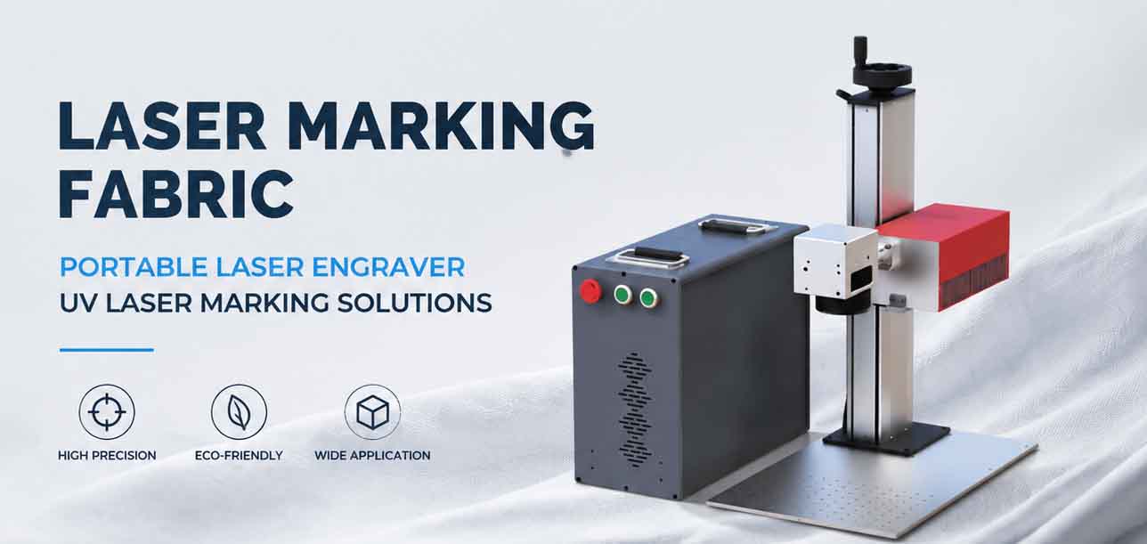
Laser Marking Fabric with Portable Laser Engraver: Advanced UV Laser Marking Solutions for Modern Manufacturing
Laser Machine for Marking: The Ultimate Guide to Portable Fiber Engravers & MOPA Color Laser Marking

Laser Cleaning Machine for Wood: The Ultimate Guide to Safe, Precise & Eco-Friendly Wood Surface Cleaning