| 3D Scanner | |||
| Aperture | 10 mm | 12 mm | 14 mm |
| Marking Speed | 6000 mm/s | 2000 mm/s | 1500 mm/s |
| Positioning Speed | 15000 mm/s | 12000 mm/s | 7000 mm/s |
| Step Response Time (1% Of Full Scale) | 300 us | 400 us | 650 us |
| Nonlinearity | < 0.4% | ||
| Tracking Error Time | 220 us | ||
| Long – Term Drift Over 8 Hours | < 0.3 mrad | ||
| Zero Offset | < 5 mrad | ||
| Input Voltage | ±15 V DC | ||
| Rated Current | 3A | ||
| Interface Signal | XY2-100 | ||
| Z Specifications | |||
| Wavelength | 355 nm | 532 nm / 1064 nm | 10600 nm |
| Beam Ratio | 1.67 / 2.0 X | 1.67 X | 1.85 X |
| Input Aperture | 5 mm – 7 mm | 6 mm – 8 mm | 5 mm – 7 mm |
| Marking Field | 150*150 mm ((± 35mm) with F=254 Lens | ||
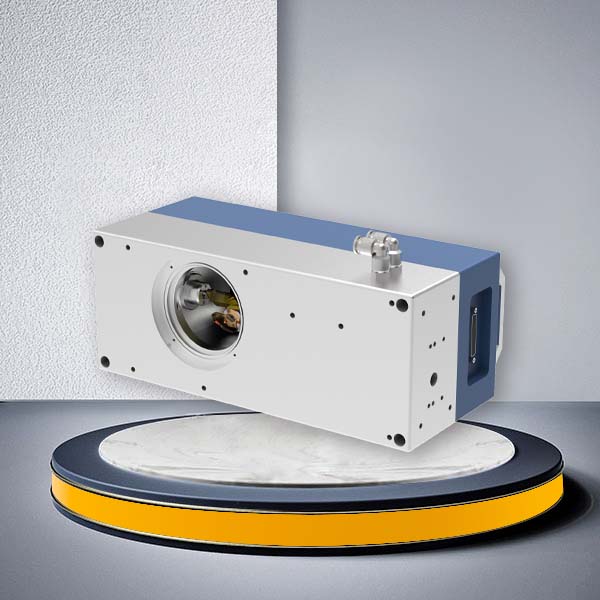
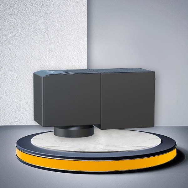
GO3D-T 3D Dynamic Focusing Galvo Scanner Head
The JCZ GO3D-T is a 3D dynamic focusing galvo scanner head designed for laser systems that need the focal position to follow changes in workpiece height rather than remain on one fixed XY plane.
The current GO3D-T series provides 10 mm, 12 mm and 14 mm scanner apertures and wavelength-specific configurations for 1064 nm fiber, 355 nm UV, 532 nm green and 10.6 μm CO₂ laser systems. Published marking speed reaches up to 6000 mm/s depending on scanner aperture.
Unlike a conventional 2D galvo scanner that mainly controls beam position in X and Y, GO3D-T adds dynamic optical focus adjustment in the Z direction. This makes the scanner suitable for curved, sloped, stepped and variable-height processing where the surface cannot remain inside one fixed focal plane.
For OEM integration, select the scanner in this order:
workpiece geometry → laser wavelength → required XY field and Z variation → input beam → scanner aperture → focusing optics → controller and software → calibration.
Is GO3D-T the Right 3D Galvo for Your System?
Use a 3D dynamic focus scanner when the processing surface changes height during the laser path.
Typical geometry includes:
- curved housings;
- sloped surfaces;
- stepped components;
- molds and cavities;
- cylindrical or partially cylindrical parts;
- raised or recessed features;
- layer-by-layer deep engraving.
A standard 2D galvo remains the simpler choice when all processing stays close to one focal plane.
A 3D galvo becomes useful when a fixed-focus system would otherwise require repeated mechanical refocusing, workpiece repositioning or additional motion axes.
Dynamic focus does not remove the need for correct optics and calibration. Final spot quality still depends on the laser beam, wavelength, lens, processing field, Z variation and workpiece geometry.
Choose the Scanner Aperture by Beam and Speed
GO3D-T is currently listed with three XY scanner apertures.
| Scanner Aperture | Published Marking Speed | Positioning Speed | 1% Step Response |
|---|---|---|---|
| 10 mm | 6000 mm/s | 15000 mm/s | 300 μs |
| 12 mm | 2000 mm/s | 12000 mm/s | 400 μs |
| 14 mm | 1500 mm/s | 7000 mm/s | 650 μs |
The largest aperture is therefore not automatically the best configuration.
10 mm — Prioritize Dynamic Speed
The 10 mm configuration has the highest published marking and positioning speeds in the current GO3D-T range.
It should be evaluated first when:
- the required beam fits the optical aperture;
- cycle time is important;
- the system uses a relatively compact beam path;
- large beam handling is not the primary requirement.
12 mm — Balance Beam Size and Dynamics
The 12 mm version provides more beam aperture while retaining higher dynamics than the current 14 mm configuration.
It is a useful direction when the optical design needs additional beam clearance but the machine still requires relatively fast contour processing.
14 mm — Evaluate for Larger Beam Requirements
The 14 mm version provides the largest scanner aperture in the current series.
It should be selected because the optical design requires the larger aperture—not simply because 14 mm appears to be a higher specification.
The current published data shows lower marking and positioning speed than the 10 mm and 12 mm versions, so beam-handling requirements should be balanced against cycle time.
Scanner Aperture and Input Beam Diameter Are Different Parameters
Scanner aperture describes the clear aperture of the XY scanning system.
The beam entering the complete 3D optical system may be smaller.
The current GO3D-T optical specifications list model-dependent Z-module input apertures of approximately 5–8 mm, depending on wavelength configuration.
When designing the system, check the complete beam path:
laser source → beam expansion/collimation → dynamic focusing module → XY scanner → focusing optics → workpiece.
An oversized beam may be clipped by an optical element even if the nominal XY scanner aperture appears sufficient.
An undersized beam may also limit the focused-spot performance that could otherwise be achieved with a larger optical aperture.
Match the Galvo to the Laser Wavelength
GO3D-T is available in configurations for the major industrial laser wavelengths currently listed by JCZ.
| Laser Wavelength | Typical System Direction |
|---|---|
| 1064 nm | Fiber-laser marking, engraving and metal processing |
| 355 nm | UV precision marking and selected electronics, polymer and glass processes |
| 532 nm | Green-laser precision processing |
| 10.6 μm | CO₂ processing of suitable non-metal materials |
These should be treated as wavelength-specific scanner configurations.
Do not assume that one optical configuration can simply be moved between 1064 nm, 355 nm and 10.6 μm laser sources.
Mirror coatings, dynamic-focus optics, beam diameter and the focusing lens must all match the selected wavelength and laser system.
Understand XY Field, Z Range and Working Distance Together
For a 3D galvo scanner, XY processing field and Z focus range should not be selected independently.
Increasing the optical field normally changes:
- focal length;
- working distance;
- focused spot;
- usable Z range;
- process resolution.
This is why the required specification should be expressed as a working volume, not only as an XY marking area.
Before selecting the GO3D-T optical configuration, define:
- maximum X dimension;
- maximum Y dimension;
- highest and lowest workpiece surface;
- required feature or line width;
- required working distance;
- laser wavelength and input beam.
The current GO3D-T specification page publishes a 150 × 150 mm field entry together with an approximately ±35 mm value using an F=254 lens. The exact interpretation and applicable wavelength/aperture combination should be confirmed against the current project datasheet before mechanical design is frozen.
For OEM projects, request the lens-specific combination of:
XY field + Z range + working distance + expected spot size.
Why Z-Axis Dynamics Matter
A 3D scanner contains three coordinated dynamic functions.
If X and Y can move rapidly but the optical Z axis cannot follow the surface profile at the required rate, the Z axis becomes the limiting element in the processing path.
This matters particularly for:
- rapidly changing curved profiles;
- dense 3D hatch patterns;
- deep engraving;
- high-speed contour marking;
- variable-height traceability.
For applications where Z motion changes continuously at high speed, provide the surface profile and target cycle time for configuration review instead of selecting the scanner only from the maximum XY marking speed.
Application-to-Configuration Selection
| Application | Main Requirement | Configuration Questions |
|---|---|---|
| Curved-surface marking | Maintain focus as height changes | Surface height range, field, code size |
| Mold/deep engraving | Move focus as material is removed | Depth, layer strategy, spot, cycle time |
| Stepped components | Rapid change between focal planes | Step height, transition speed |
| UV precision marking | Small features and wavelength-specific optics | 355 nm configuration, input beam, field |
| Glass processing | Stable focus through changing depth/geometry | Laser type, glass process, Z range |
| Large curved components | Larger field with focus compensation | Determine whether GO3D-T or large-format DTJJ is more suitable |
| Automated 3D marking | Scanner + PLC/motion coordination | DLC controller, I/O, trigger, motion |
| Cylindrical/rotary parts | Focus plus rotary/motion coordination | Rotary architecture, surface profile, cycle time |
The material name alone is not sufficient for scanner selection.
The workpiece geometry and laser process determine the required 3D optical configuration.
Curved-Surface Laser Marking
Curved workpieces create a simple problem for a fixed-focus 2D system: as surface height changes, part of the marking path moves outside the best-focus plane.
GO3D-T adds active focus adjustment so the system can follow the surface profile in Z while the galvo mirrors control X and Y.
This is relevant for parts such as:
- automotive interior components;
- curved electronic housings;
- medical-device surfaces;
- molded plastic parts;
- tools;
- decorative metal components;
- industrial parts with recessed or raised features.
For traceability applications, send the actual surface geometry rather than only the QR-code dimensions. A small code on a strongly curved surface can be more demanding than a larger code on a nearly flat part.
Deep Engraving and Relief Processing
During deep engraving, the active processing surface moves downward as material is removed.
Dynamic focus allows the focal position to be adjusted during layer-by-layer processing instead of keeping the focus at the initial workpiece surface.
The achievable engraving result depends on the complete process:
- laser source;
- pulse parameters;
- material;
- hatch strategy;
- layer depth;
- scanner dynamics;
- lens;
- calibration.
The galvo scanner alone does not determine achievable engraving depth or surface finish.
Controller and Software Compatibility
GO3D-T should be integrated as part of a compatible 3-axis laser-control architecture.
JCZ’s current EZCAD3 platform supports 3D processing and dynamic-focus functions with compatible DLC controller hardware.
A typical system may include:
- GO3D-T 3D dynamic focusing galvo scanner head;
- compatible laser source;
- DLC controller;
- EZCAD3 software;
- wavelength- and field-matched focusing optics;
- required beam-expansion optics;
- scanner and controller cables;
- machine I/O or PLC;
- motion stage or rotary axis if required.
XY2-100 describes the scanner communication interface. It should not be treated as proof that any controller/software combination will automatically support the complete XYZ processing workflow.
Confirm the exact controller model and 3D configuration before ordering.
F-Theta Lens and Optical Selection
The focusing lens affects more than the nominal marking field.
Selection should include:
- wavelength;
- input aperture;
- focal length;
- working distance;
- scan field;
- desired spot size;
- required Z variation.
JCZ currently provides F-theta lenses for industrial UV, green and infrared laser systems with multiple input apertures, focal lengths and working distances.
Do not change to a longer focal-length lens only to obtain a larger field without checking the resulting spot size and required processing resolution.
GO3D-T vs G3-3D vs DTJJ
JCZ currently provides several 3D galvo directions for different integration requirements.
| Requirement | G3-3D | GO3D-T | DTJJ |
|---|---|---|---|
| Curved-surface processing | Yes | Yes | Yes |
| Entry-level 3D system | Strong fit | Available | Less relevant |
| Multiple XY aperture options | Limited | 10 / 12 / 14 mm | Different large-format architecture |
| Published max marking speed | 4000 mm/s | Up to 6000 mm/s | Project/configuration dependent |
| Large-format processing | Limited | Medium-scale project selection | Main strength |
| OEM dynamic-focus integration | Suitable | Strong fit | Strong fit for large fields |
G3-3D is a practical direction for entry-level post-focus 3D integration.
GO3D-T should be considered when the project requires a broader combination of aperture choice, wavelength configuration and dynamic performance.
DTJJ should be evaluated when large-format processing is the primary requirement.
Final selection should be based on the required working volume and optical system rather than the product hierarchy alone.
JCZ 3D Laser Control Ecosystem
Beijing JCZ Technology Co., Ltd. was founded in 2004 and focuses on laser beam-delivery and control research, development, manufacturing and integration. Its current product portfolio includes laser control software, controllers, galvo scanners, laser sources and laser optics for laser-system integrators.
This system-level product range is relevant to a 3D dynamic focusing project because scanner selection cannot be separated from the controller, software, laser source and focusing optics.
For a new OEM project, provide the complete machine architecture during technical review rather than purchasing the 3D scanner as an isolated component.
Ready to add true 3D capability to your laser marking system?
Contact us today for 3D galvo scanner head samples, detailed datasheets, lens recommendations, or a personalized quote on custom 3D dynamic focusing galvo head manufacturer solutions. Fast response guaranteed for OEM and industrial inquiries.