A galvo mirror scanner converts controller commands into rapid angular movement of two or more reflective mirrors, directing a laser beam across a defined working field. For an industrial buyer, however, the real question is not simply how the device works. The purchasing decision is whether the scan head will match the laser wavelength, beam diameter, lens, controller, processing field, cycle time and accuracy requirement of the complete machine.
Selecting by price or headline speed alone can cause an undersized aperture, incorrect mirror coating, unstable long-shift performance, distorted field calibration or incompatibility with the existing controller. This guide explains how OEM machine builders, system integrators, distributors and maintenance teams can specify a complete laser scanning subsystem rather than buying an isolated component.
Galvo Mirror, Galvanometer and Scan Head: What Is the Difference?
A galvo mirror is the reflective optical element attached to a galvanometer motor. The motor changes the mirror angle in response to an electrical command. A two-axis scan head normally uses an X-axis and Y-axis galvanometer to position the laser beam across a flat field. A three-axis system adds dynamic focusing so that the focal position can change for curved surfaces, height variation, larger fields or controlled depth processing.
International buyers may use several names for the same general product category:
- Galvanometer mirror scanner
- Laser galvo scanner
- Galvo scan head
- Laser scan head
- Optical scanning head
- XY galvo system
- Galvanometer scanner
- Beam-steering scanner
These terms are related, but “galvo mirror” alone may also refer only to the replacement optical mirror. Buyers seeking a complete assembly should specify the scan head, drive electronics, interface, cables and calibration requirements.
How to Select a Galvo Mirror Scanner for a Real Machine Project
1. Match the Mirror Coating to the Laser Wavelength
The reflective coating must be designed for the laser wavelength. Common industrial configurations include 355 nm ultraviolet, 532 nm green, approximately 1064 nm fiber or infrared, and 9.3–10.6 μm CO₂ systems.
A scanner advertised for one wavelength should not be assumed suitable for another. An incorrect coating can reduce usable process power, increase thermal loading and damage the optical surface.
The wavelength should be confirmed for every new system and replacement order.
2. Match the Optical Aperture to the Incoming Beam
The scanner’s clear aperture must accommodate the expanded laser beam without clipping. A larger aperture can accept a larger beam and may help produce a smaller focused spot, but larger mirrors also have greater inertia. This can affect acceleration and dynamic response.
The correct choice balances:
- Input beam diameter
- Required focused spot
- Field-lens entrance aperture
- Working field
- Process power
- Dynamic speed
- Available installation space
Do not select a 10 mm, 14 mm, 20 mm or larger system from aperture alone. The beam expander, scanner and field lens should be evaluated as one optical chain.
3. Decide Between 2D and 3D Scanning Before Comparing Models
A two-axis scan head is normally the most economical solution for flat marking, coding, engraving, trimming and other processes performed within the usable focal depth of the lens.
Adding a third axis does not automatically improve every flat-marking machine. It introduces additional optical, calibration, software and controller requirements. The workpiece geometry and processing objective should determine the architecture.
4. Compare Dynamic Performance Using the Right Metrics
Maximum marking speed alone does not predict production performance.
A scan head may reach a high no-load positioning speed but still produce rounded corners, inconsistent hatch spacing or distorted small characters when the command path exceeds its dynamic capability.
5. Evaluate Accuracy, Repeatability and Thermal Drift Separately
Accuracy describes how closely the beam reaches the commanded position after calibration. Repeatability describes whether it returns to the same position. Thermal drift describes how the position changes as the system warms up or operates over a long shift.
For long production runs, ask for gain drift, offset drift and drift-over-time data rather than relying only on a general “high precision” description.
6. Confirm the Field Lens and Working-Distance Combination
The scan head directs the beam, while the F-theta or telecentric lens determines much of the usable field, working distance and spot behavior.
Increasing field size normally changes the focused spot and energy density. A larger field is therefore not a free upgrade.
For a new machine, selecting the scanner, beam expansion and lens as one subsystem reduces compatibility risk.
7. Check Controller Protocol, Resolution and Software Compatibility
The scan head must communicate correctly with the laser controller. Confirm:
A controller mismatch may cause no movement, reversed axes, scaling errors, unstable operation or poor interpolation.
Compatible controller hardware can coordinate the laser source, scan head, encoder, I/O and motion functions as one system. For example, the DLC2-V2 Laser and Galvo Controller supports enhanced three-axis scan-head communication, industrial I/O, encoder inputs and project-based motion expansion.
8. Consider Laser Power, Duty Cycle and Cooling
High average power, high duty cycle and heat-sensitive coatings may require additional thermal management.
Depending on the process, cooling may be required around:
- Entrance aperture
- Scanner electronics
- Galvanometer motors
- Deflection mirrors
- Protective optics
Average power alone may not describe the full optical load. For demanding applications, send the pulse energy, repetition rate, pulse width, beam diameter and expected duty cycle.
Welding, cleaning and high-power cutting projects should be evaluated differently from standard low-power marking.
9. Confirm Mechanical and Environmental Integration
The quotation should cover more than optical specifications.
These details determine whether the scan head can be installed without redesigning the machine enclosure or optical path.
Product Directions for Different Applications
Standard 2D Marking, Engraving and Coding
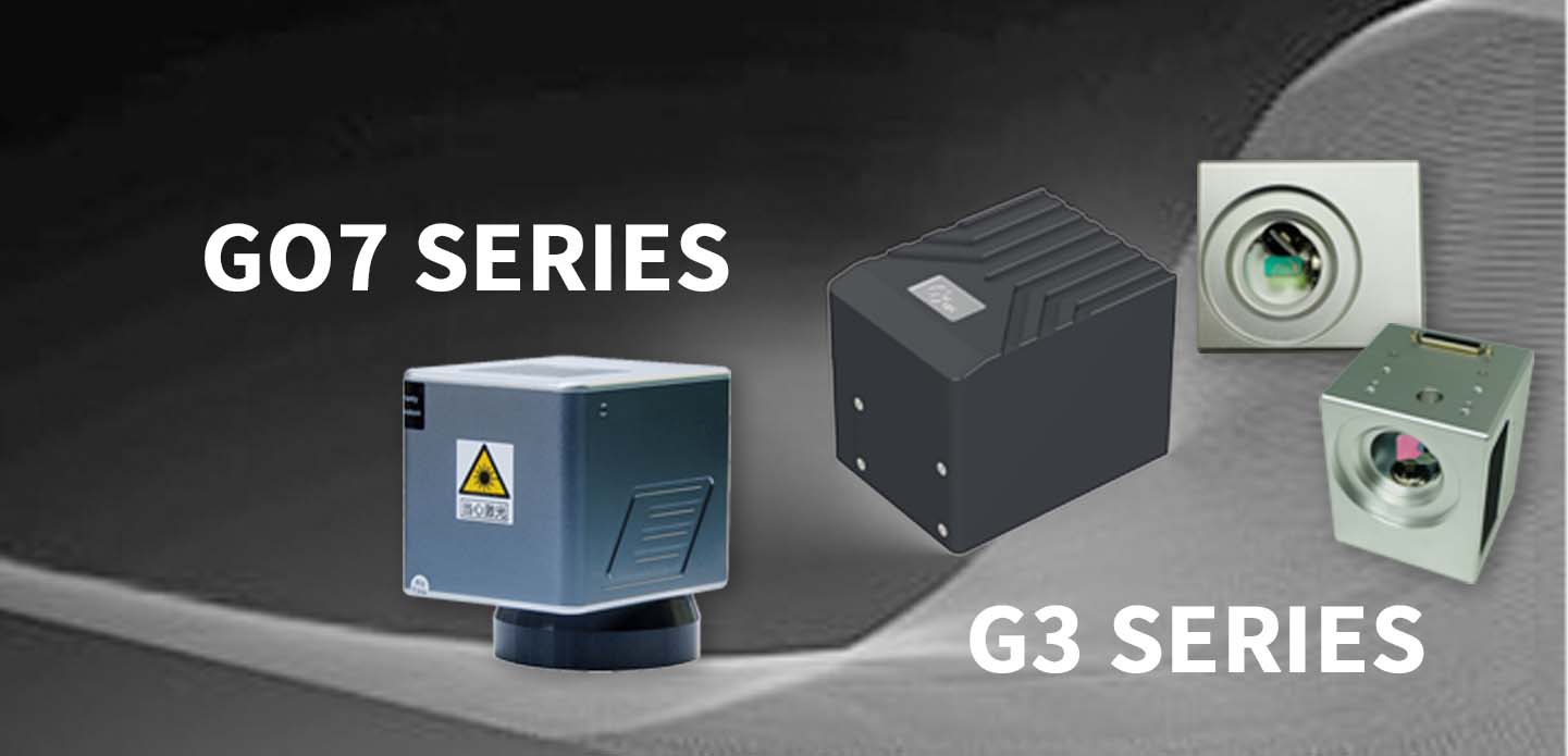
The GO7 Series 2D Galvo Scanner Head is intended for high-speed 2D laser processing across commonly used industrial wavelengths.
The G3 Series 2D Galvo Scanner provides Base, Standard and Ultimate configurations for different balances of cost, speed, linearity, drift and process stability.
The published G3 family specifications include:
- 10 mm scanner input diameter
- XY2-100 interface
- CO₂, infrared, green and ultraviolet wavelength options
- Different speed and drift levels across the three configurations
The correct version should be selected from the required feature quality, cycle time, stability and project budget rather than by model name alone.
Curved Surfaces, Height Variation and 3D Processing
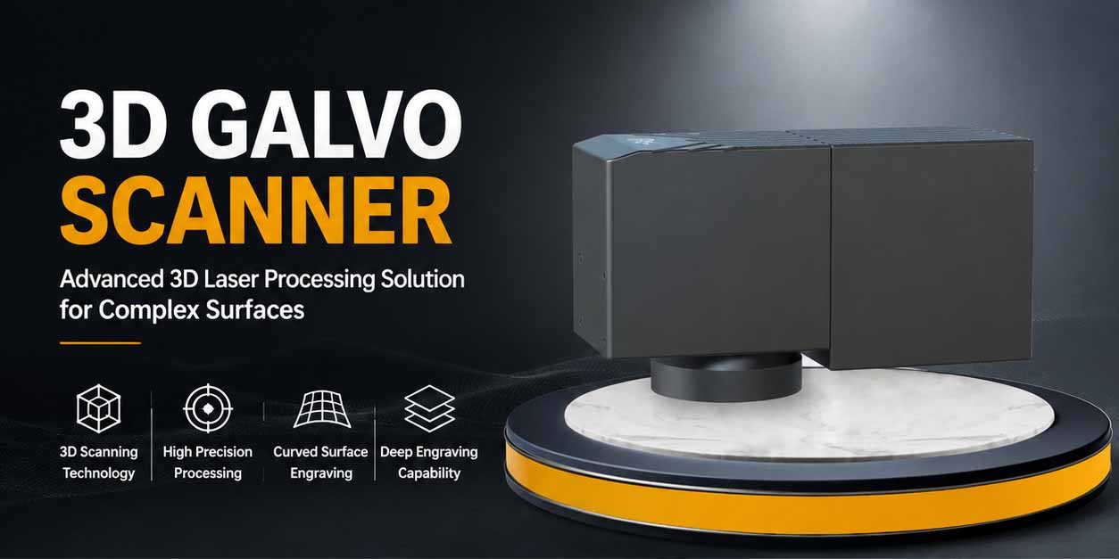
The G3-3D Industrial 3D Galvo Head combines X-Y scanning with a third-axis focusing module. It is intended for curved-surface processing, deep engraving, drilling, micromachining and other applications requiring focal-position control.
Its published configuration includes XY2-100 communication, multiple wavelength options and dynamic focusing for height-varying processing.
The GO3D-T 3D Galvo Scanner Head is another option for precision 3D engraving and dynamic-focus projects.
For larger pre-focus configurations, review the Dynamic Focus Galvo System and provide the required field, working distance and surface geometry.
High-Power Laser Welding
The G3 Weld Galvo Scanner is the relevant product direction for welding projects.
The final configuration should be reviewed against:
- Laser wavelength
- Laser power
- Beam diameter
- Weld path
- Protective optics
- Cooling
- Duty cycle
- Required working field
Welding applications should not use a standard marking scan head without verifying thermal and optical suitability.
Complete Product Range
Review the Galvo Scanner Product Range for available 2D, 3D, dynamic-focus and welding scan-head directions. The current range includes 2D G3 and GO7 products, multiple 3D architectures and a dedicated welding direction.
When a Galvo Mirror Scanner Should Be Replaced
Replacement is appropriate when troubleshooting confirms that the scan head—not the controller, lens, cable, power supply or calibration file—is causing the defect.
Typical symptoms include:
- Characters becoming wavy or distorted
- Intermittent axis movement
- Excessive noise from one axis
- Unstable position after warm-up
- Increasing offset during a production shift
- One axis failing to respond
- Repeated scanner-electronics alarms
- Failure to complete calibration
- Visible mirror contamination
- Damaged mirror coating
Before replacing the assembly, inspect:
- Power supply
- Scanner cables
- Grounding
- Controller output
- Correction file
- Lens condition
- Mechanical mounting
- Environmental temperature
Replacing only the mirror is not always practical because mirror alignment, balancing and servo tuning affect the complete galvanometer assembly.
Common Purchasing Mistakes
Buying by Maximum Speed Alone
Headline speed does not guarantee small-character quality, corner accuracy or stable performance at the required hatch density.
Treating All Mirrors as Interchangeable
Mirror coating, aperture, substrate, thickness, mounting and balance must suit the scanner and wavelength.
Ignoring the Lens and Beam Expander
The scanner cannot compensate for an incorrectly selected optical chain.
Assuming Any Controller Can Drive Any Scan Head
Protocol, command resolution, cable pinout and three-axis support must match.
Using a 3D System for a Basic Flat Application
Additional complexity is justified only when the geometry or process requires dynamic focus.
Replacing the Scanner Before Diagnosing the System
Power, grounding, cables, calibration, the field lens and controller output should be checked first.
Why Work with JCZ for Scanner and Control Integration?
JCZ was founded in 2004 and focuses on laser beam delivery and control research, development, manufacturing and integration. Its product range covers control software, controller boards, galvo scanning systems and optical components.
For an OEM or system integrator, this means the scan head can be evaluated together with:
- Laser controller
- Control software
- Laser interface
- Galvo protocol
- Field lens
- Calibration requirements
- Motion axes
- External I/O
This subsystem-level approach is especially useful for controller replacements, 3D systems, automation projects and applications where calibration or protocol compatibility directly affects the final processing result.
Frequently Asked Questions
Is a Galvo Mirror the Same as a Complete Scan Head?
No. The mirror is one optical component. A complete scan head also includes galvanometer motors, position sensing, drive electronics, housing, cables and factory alignment.
Can One Scanner Work with Fiber, UV, Green and CO₂ Lasers?
Only when the optical configuration is designed for the required wavelength range. Confirm the mirror coating, lens and other optical components before ordering.
Does a Larger Aperture Always Produce Better Results?
No. A larger aperture can accept a larger beam, but it may also increase moving mass. The choice must balance spot requirements, lens size, speed and system dynamics.
Is 3D Scanning Required for Deep Engraving?
Not always. Layered deep engraving on a flat surface may be possible with a 2D system and Z-axis adjustment. Dynamic focus becomes more valuable when focal position must change continuously across depth, height or curved geometry.
Why Does Marking Shift After the Machine Warms Up?
Possible causes include scanner drift, lens or mount expansion, control-electronics temperature, grounding or mechanical instability. Diagnose the complete optical and control chain before replacing parts.
What Should Be Tested Before Batch Purchasing?
Use the actual laser, lens, material, file, field size and target cycle.
Evaluate:
- Edge quality
- Small characters
- Hatch uniformity
- Corner behavior
- Position repeatability
- Stability after warm-up
- Performance over a full shift
Request a Technical Configuration Review
For a galvo mirror scanner recommendation, send your laser model, wavelength, beam diameter, controller protocol, field lens, working area, target speed, accuracy requirement and application samples through the Contact Page.
JCZ can then recommend a 2D, 3D or welding scan-head direction and identify the controller, software and optical information that must be confirmed before quotation.
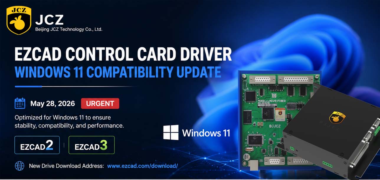
OFFICIAL DRIVER UPDATE NOTICE
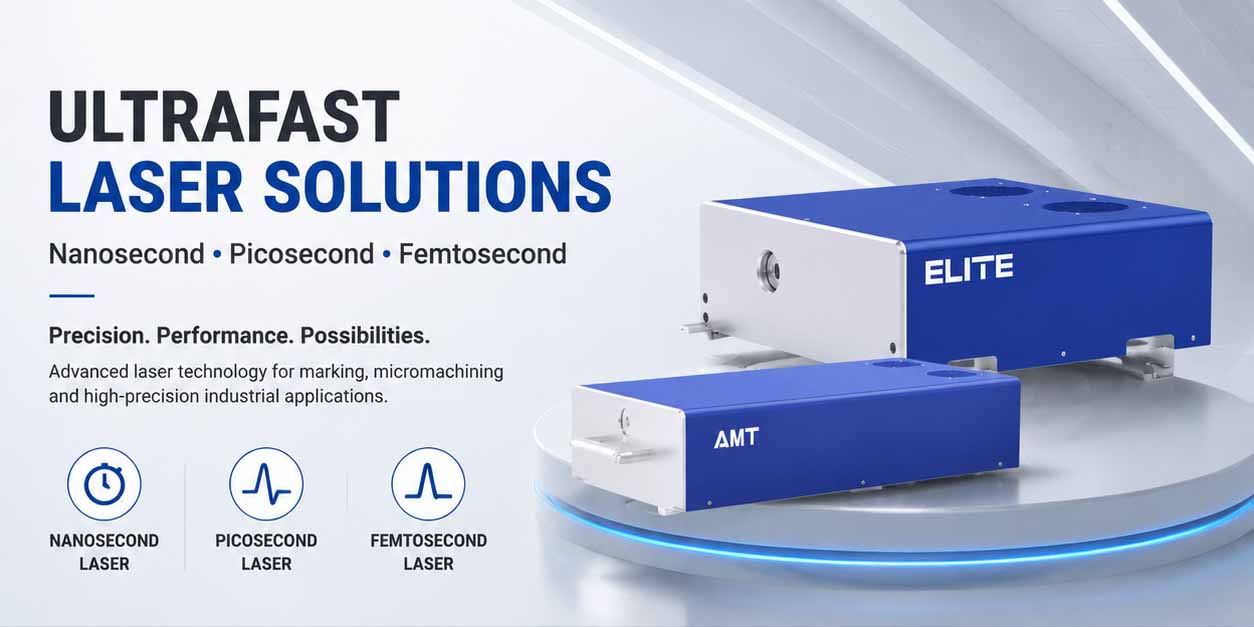
Nanosecond Laser vs Picosecond Laser vs Femtosecond Laser: Complete Guide to Ultrafast Laser Technology

Fiber Laser vs CO2 Laser vs UV Laser: How to Choose the Right Laser Solution for Your Application?
Open-Frame vs Enclosed Laser Marking Machines for Production
Laser Control Board: The Core Technology Behind High-Precision Laser Processing Systems
3D Galvo Scanner: Advanced Solution for Complex Surface Laser Engraving and 3D Marking